

Controlled delivery system for bioactive substances
- Summary
- Abstract
- Description
- Claims
- Application Information
AI Technical Summary
Benefits of technology
Problems solved by technology
Method used
Image

Examples
example 1
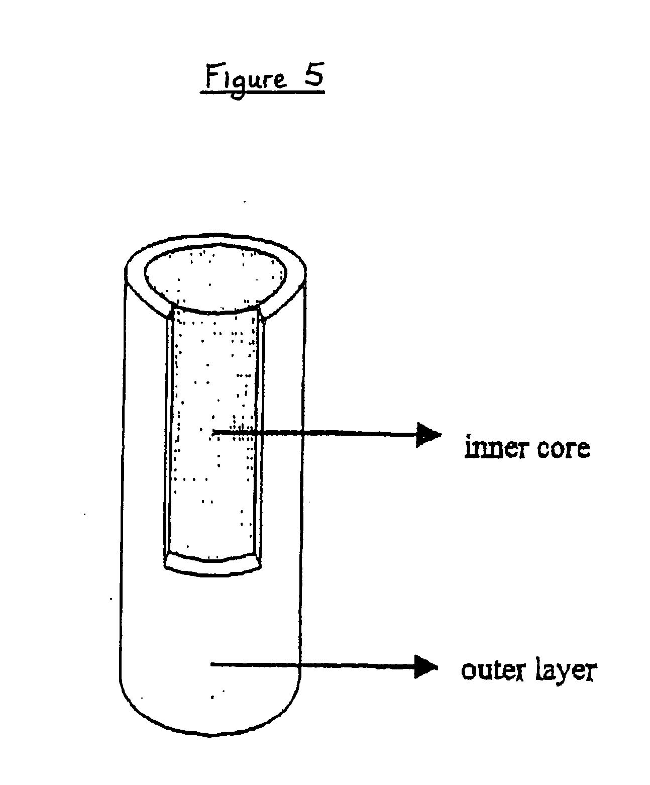
[0082] In order to obtain a system suitable for drug sustained release, we produced an “open reservoir” system consisting of a hot stage extruded ethylcellulose pipe surrounding a drug-containing Gelucire®-HPMC matrix. An exemplary production procedure of all systems tested herein-after is as follows. Extrusion was performed on a MP19 TC25 laboratory intermeshing co-rotating twin screw extruder of APV-Baker (Newcastle-under-Lyme, United Kingdom). For the production of the outer layers (pipes), ethylcellulose and 20% dibutyl sebacate (based on the ethylcellulose polymer weight) acting as a plasticizer were extruded under the following conditions: screw speed of 5 rpm, powder feed rate of 0.29 kg / h and a temperature profile of 125-125-115-105-80° C. from powder feed to die. The extrudates (having an internal diameter of 5 mm and a wall thickness of 1 mm) were cut into pieces of 1 to 2 cm. The inner core (matrix) mixture consisted of 5% by weight theophylline monohydrate (available fro...
example 2
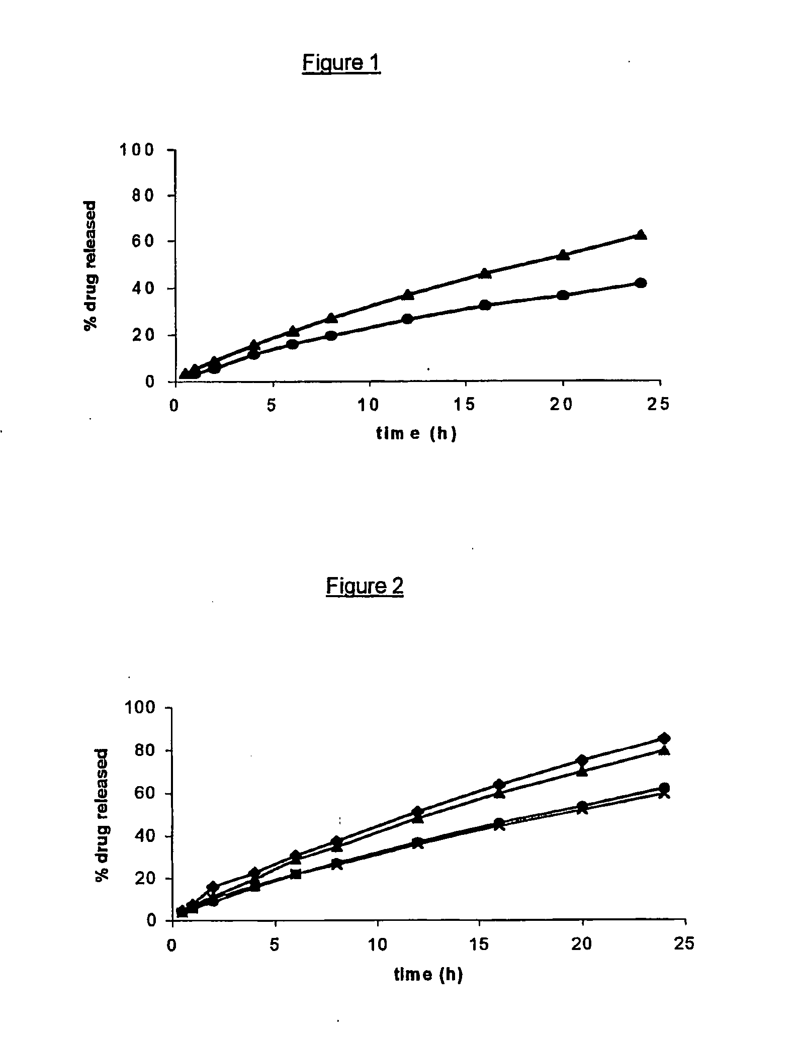
[0084]FIG. 1 represents the drug release profiles of two open reservoir delivery systems. (composite articles) according to the invention, each including 5% by weight theophylline monohydrate as a drug but including different grades of HPMC in the inner core. The latter consisted of 5% by weight theophylline monohydrate, 30% by weight Methocel® K100 (▴) or Methocel® K100M (●) and 65% by weight Gelucire® 44 / 14, and was surrounded by an outer layer (pipe) comprising a 100:20 (by weight) mixture of ethylcellulose and dibutyl sebacate. FIG. 1 shows that Methocel® K100M provides a more prolonged sustained release than Methocel K100, all other parameters being kept equal.
example 3
[0085]FIG. 2 represents the drug release profiles of four open reservoir delivery systems (composite articles) according to the invention, each including 5% by weight of the same drug in the inner core but with outer layers (pipes) having different dimensions. Each inner core (matrix) contained 5% by weight theophylline monohydrate, 30% by weight Methocel® K100 and 65% by weight Gelucire® 44 / 14, and was surrounded by an outer layer (pipe) comprising a 100:20 (by weight) mixture of ethylcellulose and dibutyl sebacate. The said pipe had, respectively, a length of 18 mm and an internal diameter of 5 mm (●); a length of 18 mm and an internal diameter of 7 mm (X); a length of 12 mm and an internal diameter of 5 mm (▴); and finally a length of 12 mm and an internal diameter of 7 mm (♦).
PUM
| Property | Measurement | Unit |
|---|---|---|
| Temperature | aaaaa | aaaaa |
| Temperature | aaaaa | aaaaa |
| Percent by mass | aaaaa | aaaaa |
Abstract
Description
Claims
Application Information