Plasma processing device

Inactive Publication Date: 2006-01-12
TOKYO ELECTRON LTD
View PDF7 Cites 7 Cited by
  • Summary
  • Abstract
  • Description
  • Claims
  • Application Information

AI Technical Summary

Benefits of technology

[0016] The present invention has been made for resolving the aforementioned problems, and it is therefore an object of the present invention t

Problems solved by technology

As described above, since the plasma density cannot be further increased in the plasma generation region 122 and the uniformity of the plasma density di

Method used


Image

  • Plasma processing device
  • Plasma processing device
  • Plasma processing device

Examples


Embodiment Construction

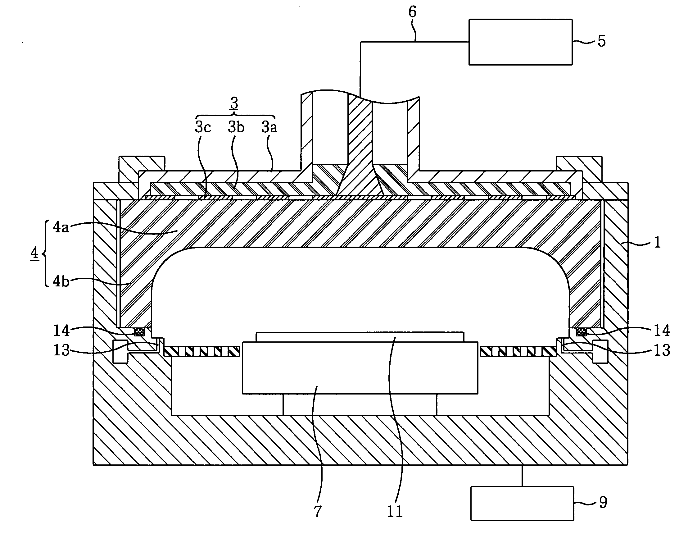
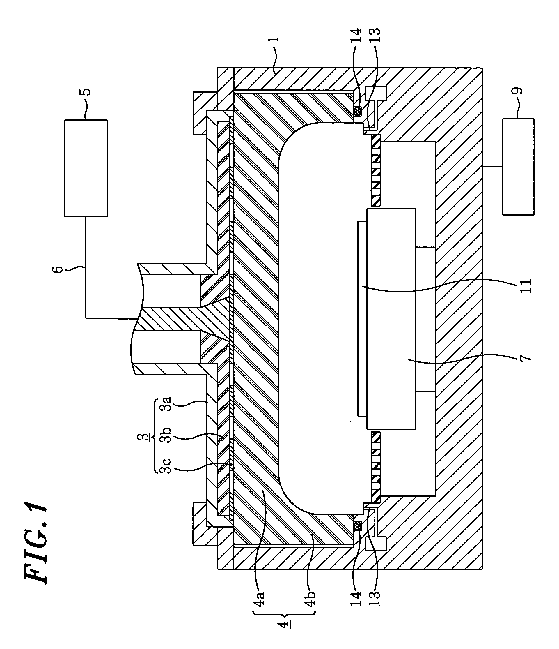
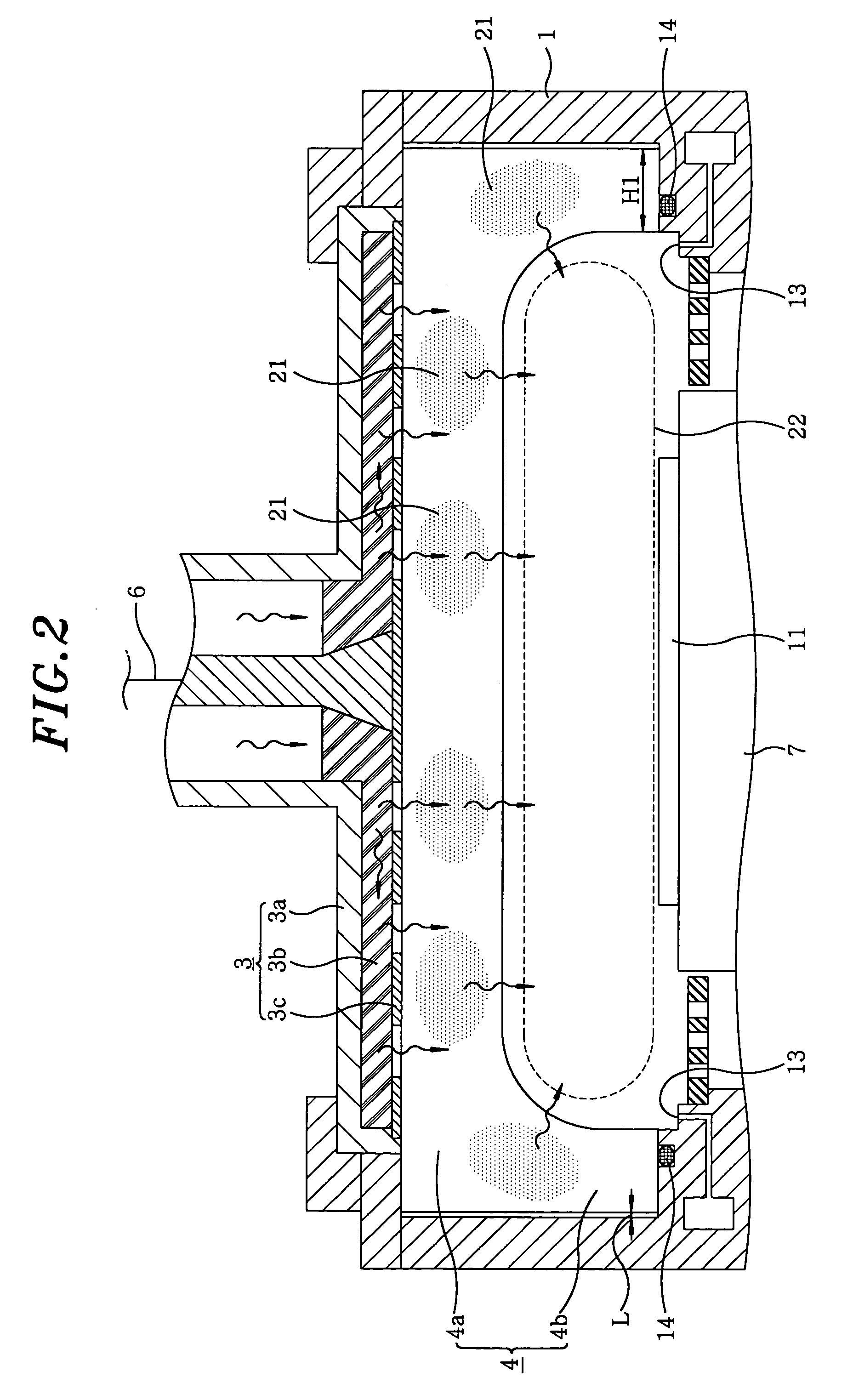
[0035] A plasma processing apparatus in accordance with the present invention will now be described. As shown in FIG. 1, the plasma processing apparatus includes a chamber 1 accommodating therein a substrate 11 and performing a predetermined processing on the substrate 11; a high frequency power supply 5 for generating a microwave; and an antenna unit 3 for irradiating the microwave into the chamber 1.

[0036] The antenna unit 3 is comprised of a slot plate 3c, a wave retardation plate 3b, and an antenna cover 3a. The slot plate 3c is made of, e.g., a copper plate having a thickness of about 0.1 mm˜several mm. The slot plate 3c is provided with a plurality of slots (openings) for irradiating the microwave towards the inside of the chamber 1. The microwave generated from the high frequency power supply 5 is provided to the antenna unit 3 by a waveguide 6.

[0037] In the chamber 1, a susceptor 7 for supporting the substrate 11 on which a predetermined plasma processing is carried out is...


PUM

PropertyMeasurementUnit
Thicknessaaaaaaaaaa
Densityaaaaaaaaaa
Shapeaaaaaaaaaa

Abstract

A plasma processing device comprising a chamber (1), a high-frequency power supply and an antenna unit (3). The antenna unit (3) comprises a slot plate (3c) , a slow wave plate (3b) and an antenna cover (3a) . A top plate unit (4) having a flat plate (4a) and sidewalls (4b) is disposed at the upper portion of the chamber (1). The flat plate (4a) contacts the slot plate (3c) disposed to face a housed substrate (11). The sidewalls (4b) are formed so as to extend toward a substrate-disposed side from the periphery of the flat plate (4a) . The outer periphery surfaces of sidewalls (4b) contact the chamber (1). The thickness of the sidewalls (4b) is set to be at least λg/4, where λg is the wavelength of a microwave based on the permittivity of the top plate (4). Accordingly, a plasma density can be further increased and a uniformity in plasma density distribution can be improved.

Description

FIELD OF THE INVENTION [0001] The present invention relates to a plasma processing apparatus; and more particularly, to a plasma processing apparatus for performing a predetermined process on a substrate by a plasma generation region formed by introducing a microwave into a chamber. BACKGROUND OF THE INVENTION [0002] With a recent trend toward a high density and miniaturation of semiconductor devices, plasma processing apparatus have been used to perform such processes as film forming, etching, ashing, and the like in a fabrication process of the semiconductor devices. Specifically, in a microwave plasma processing apparatus for producing a plasma using a microwave, the plasma can be produced stably under a relatively low pressure (high vacuum) condition of about 0.1˜10 Pa. Thus, the microwave plasma processing apparatus using, e.g., a microwave having a frequency of 2.45 GHz has attracted considerable attention. [0003] An example of such a conventional plasma processing apparatus w...

Claims


Application Information

Patent Timeline
IPC IPC(8): B05B5/025C23C16/00B05C5/02H01J37/32
CPCH01J37/32458H01J37/32192
Inventor ISHIBASHI, KIYOTAKANOZAWA, TOSHIHISA
Owner TOKYO ELECTRON LTD
Why Eureka
Try Eureka