Process for producing a transparent optical element, optical component involved in this process and optical element thus obtained

a technology of transparent optical elements and process steps, applied in the direction of optical radiation measurement, spectales/goggles, instruments, etc., can solve the problems of difficult implementation of methods, large loss of method attraction over conventional methods, and inability to lend themselves well to mass production, etc., to avoid excessively large cells, avoid undesirable diffractive effects, and achieve high fill factor of the optical surface

Active Publication Date: 2006-01-12
ESSILOR INT CIE GEN DOPTIQUE
View PDF27 Cites 76 Cited by
  • Summary
  • Abstract
  • Description
  • Claims
  • Application Information

AI Technical Summary

Benefits of technology

[0021] Thus, within the context of the invention, it will be possible to give the cells dimensions of greater than 1 μm parallel to the surface of the component. In particular, these cell dimensions parallel to the surface of the component may be between 5 μm and 100 μm. In the application to ophthalmic optics, it may be desirable to avoid excessively large cells, something which would give the surface of the lenses a visible texture. Advantageously, the cells may have a dimension of between 10 μm and 40 μm.
[0022] Parallel to the surface of the component, the cells will preferably be separated by walls with a thickness of between 0.10 μm and 5 μm. In a first embodiment of the invention, the walls have a thickness of between 0.10 μm and 5 μm, and preferably between 0.10 μm and 0.35 μm, so that they also produce virtually no undesirable diffractive effects in the visible spectrum. Such thin walls may provide a very high fill factor τ of the optical surface with the substance having a beneficial optical effect.

Problems solved by technology

Although this provides for manufacture for each treatable case of ametropia, the method does not lend itself well to mass production.
In this case, the need to carry out a re-forming operation on the lenses means that a great deal of the attraction of the method over the conventional methods is lost.
Control of the physical phenomena of interaction between the drops and the substrate, during both deposition and solidification, makes this method very difficult to put into practice.
Furthermore, its use on a large scale is problematic since, here again, the index modulation is obtained during the manufacture of the solid object constituting the lens, and the subsequent customization assumes that a re-forming operation is carried out on the lens.
It is not possible to cut the lens in order to fit it to another frame.
It is also difficult to adapt it to the ametropia of a lens to be corrected.

Method used


Image

  • Process for producing a transparent optical element, optical component involved in this process and optical element thus obtained
  • Process for producing a transparent optical element, optical component involved in this process and optical element thus obtained

Examples


Embodiment Construction

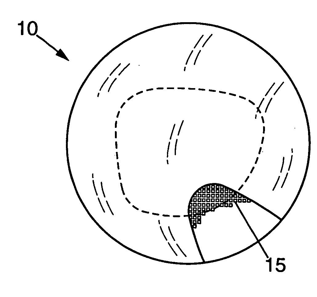
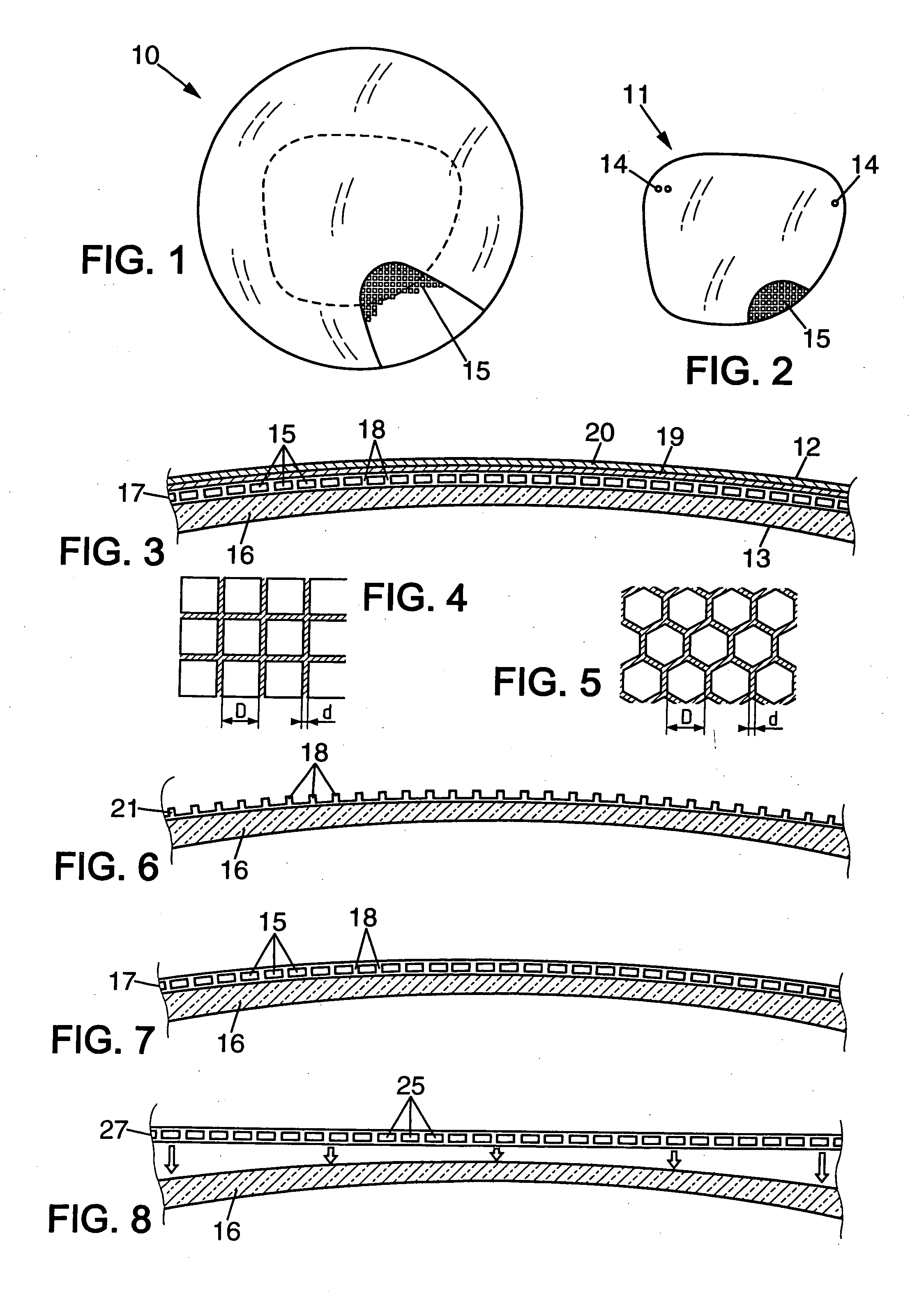
[0039] The optical component 10 shown in FIG. 1 is a blank for a spectacle lens. A spectacle lens comprises an ophthalmic lens. The term “ophthalmic lens” is understood to mean a lens that is fitted to a spectacle frame in order to protect the eye and / or correct the sight, these lenses being chosen from afocal, unifocal, bifocal, trifocal and varifocal lenses.

[0040] Although ophthalmic optics is the preferred field of application of the invention, it will be understood that this invention is applicable to transparent optical elements of other types, such as for example lenses for optical instruments, filters, optical sight lenses, eye visors, optics for illumination devices, etc. Included within the invention in ophthalmic optics are ophthalmic lenses, but also contact lenses and ocular implants.

[0041]FIG. 2 shows a spectacle lens 11 obtained by cutting the blank 10 around a predefined outline, shown by the broken line in FIG. 1. In principle, this outline is arbitrary, provided t...


PUM


Abstract

To produce a transparent optical element, the process starts with the production of an optical component having at least one transparent array of cells that are juxtaposed parallel to one surface of the component, each cell being hermetically sealed and containing a substance having an optical property. This optical component is then cut along a defined contour on its surface, corresponding to a predetermined shape of the optical element. Preferably, the array of cells constitutes a layer having a height of less than 100 μm perpendicular to the surface of the component.

Description

BACKGROUND OF THE INVENTION [0001] The present invention relates to the production of transparent elements incorporating optical functions. It applies especially to the production of ophthalmic lenses having various optical properties. [0002] Ametropia-correcting lenses are conventionally manufactured by the forming of a transparent material having a refractive index higher than that of air. The shape of the lenses is chosen so that the refraction at the material / air interfaces causes suitable focussing onto the retina of the wearer. The lens is generally cut so as to fit into a spectacle frame, with appropriate positioning relative to the pupil of the corrected eye. [0003] It is known to vary the refractive index within the material of an ophthalmic lens, thereby making it possible to limit the geometrical constraints (see for example EP-A-0 728 572). This method was proposed above all for contact lenses. The index gradient is obtained for example by diffusion, selective irradiatio...

Claims


Application Information

Patent Timeline
Patent Type & Authority Applications(United States)
IPC IPC(8): G01J5/02G02B11/00G02B5/32
CPCG02C7/101G02C7/102G02C7/083G02C2202/14G02C2202/18G02C7/12G02B3/00G02C7/02G02C7/08G02F1/1333
Inventor CANO, JEAN-PAULBOVET, CHRISTIAN
Owner ESSILOR INT CIE GEN DOPTIQUE
Why Eureka
Try Eureka