Receiver coil array for a magnetic resonance imaging system

a magnetic resonance imaging and receiver coil technology, applied in the field of receiver coil array for magnetic resonance imaging (mri) system, can solve the problems of reducing the life span of the receiver coil, noise and affecting the received signal, and coupling is a type of interference in the circuit, so as to increase the voltage of the mri system and not increase the loss of the circui

Inactive Publication Date: 2006-01-12
SIEMENS HEALTHCARE GMBH
View PDF9 Cites 6 Cited by
  • Summary
  • Abstract
  • Description
  • Claims
  • Application Information

AI Technical Summary

Benefits of technology

[0013] An object of the present invention is to provide a receiver coil array for an MRI system having a decoupling circuit, which can overcome the problem that the receiver coil in existing technology can not be shut off completely, requiring the transmitting power of the transmitter coil to be increased to compensate the signals offset, i.e. the disadvantage of increasing the voltage of the MRI system, without increasing the loss of the circuit.

Problems solved by technology

Coupling is a type of interference in the circuit.
The coupling not only results in noise and affects the received signal, but also may reduce the life span of the receiver coil due to excessive induced current.
Generally, however, decoupling can be performed only between two loop coils, and it is very difficult to perform decoupling among three or more loop coils.
First, since the magnetic flux is proportional to the signal-to-noise ratio (SNR), and the magnetic fluxes at the center of the two outer loop coils (Ring1, Ring2) are offset with respect to each other, the signal-to-noise ratio of the signals received at the center of the coil is not improved.
Further, since the signal received at the center of the receiver coil is the strongest, and the signal becomes weaker as the distance from the center becomes larger to a point where it cannot be detected, the field of view (FOV) is thus limited.
However, there are still some problems in this method.
This will lead to a change in the original detuning frequency so that it is no longer the characteristic frequency of the system, and as a result, the receiver coil cannot be completely shut off when the transmitter coil is transmitting signals.
Therefore, the receiver coil will generate some interference to the signals transmitted by the transmitter coil and offset some of them.
Therefore, if the detuning loop of a receiver coil loop operates, the decoupling of the other two coils will be affected.
Disadvantages of this method are as follows.
First, since the coupling may be inductive, capacitive or resistive, although this method may offset the inductive coupling and the capacitive coupling to some extent, it cannot compensate the resistive coupling.
Therefore, if the direction of the decoupling in the circuit is incorrect, the capacitance will be changed to an inductance with opposite character; or when an inverter is added, since the inductance will introduce certain resistance, additional loss will be brought to the circuit.

Method used


Image

  • Receiver coil array for a magnetic resonance imaging system
  • Receiver coil array for a magnetic resonance imaging system
  • Receiver coil array for a magnetic resonance imaging system

Examples


first embodiment

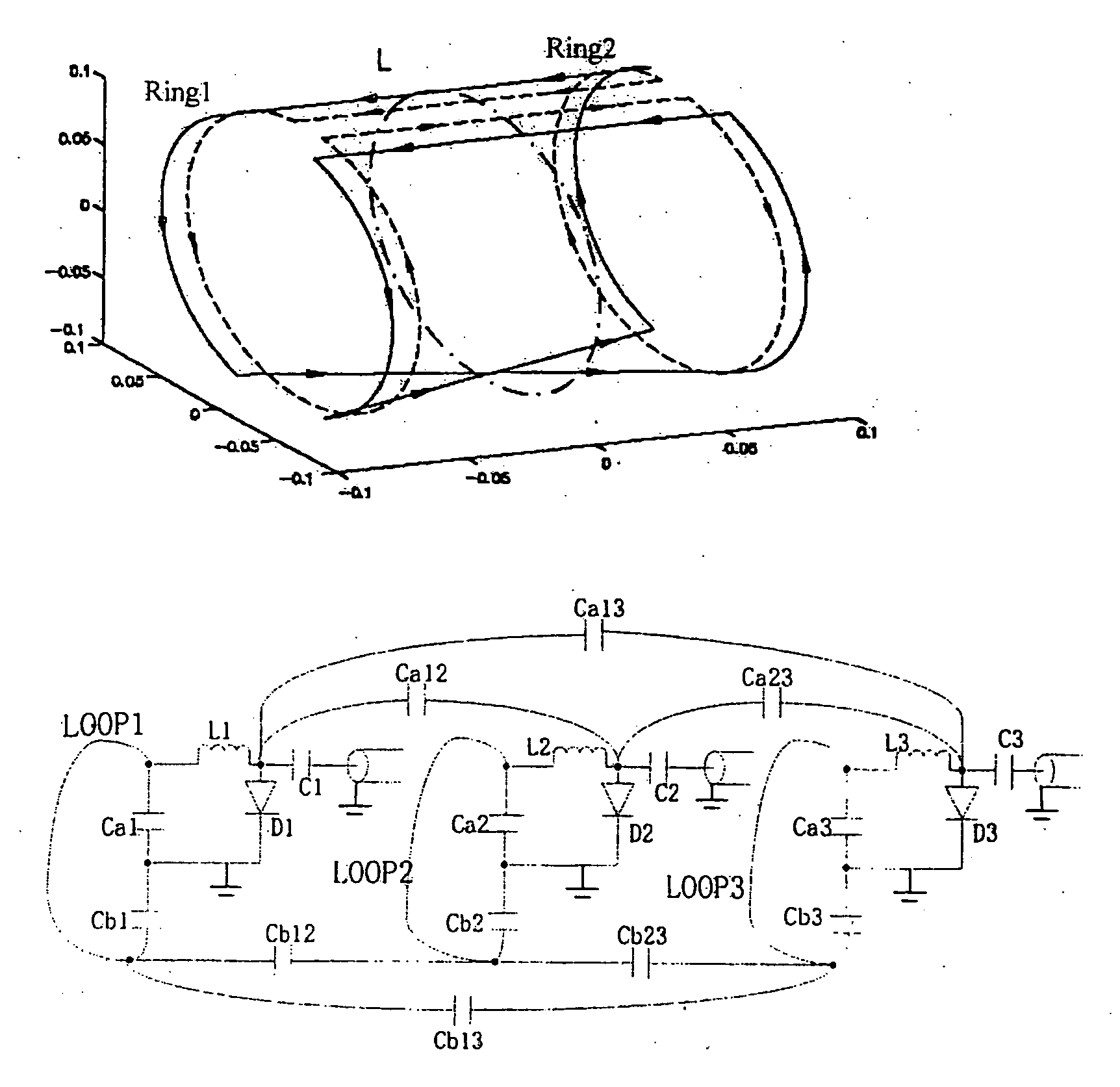
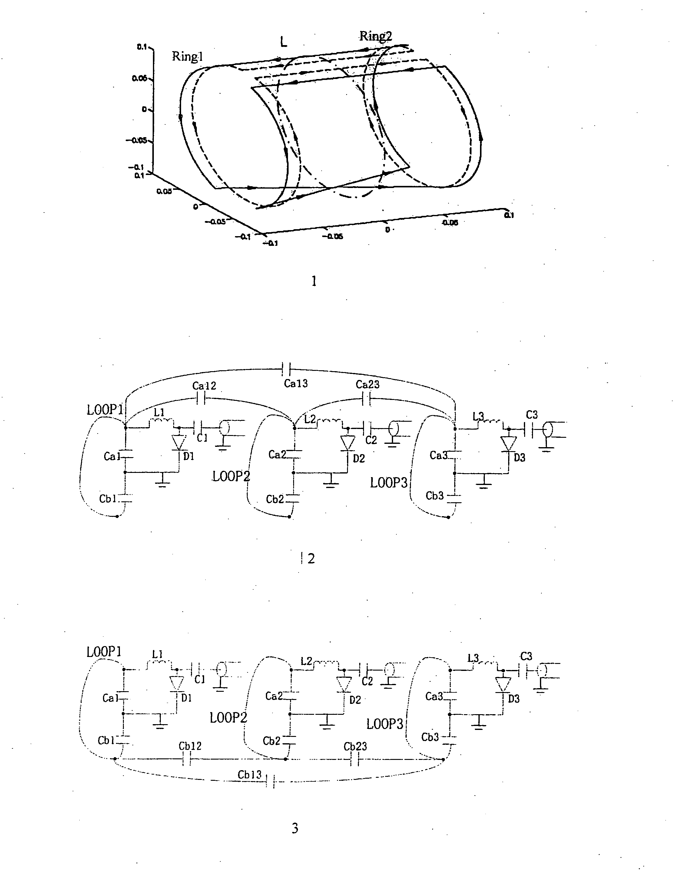
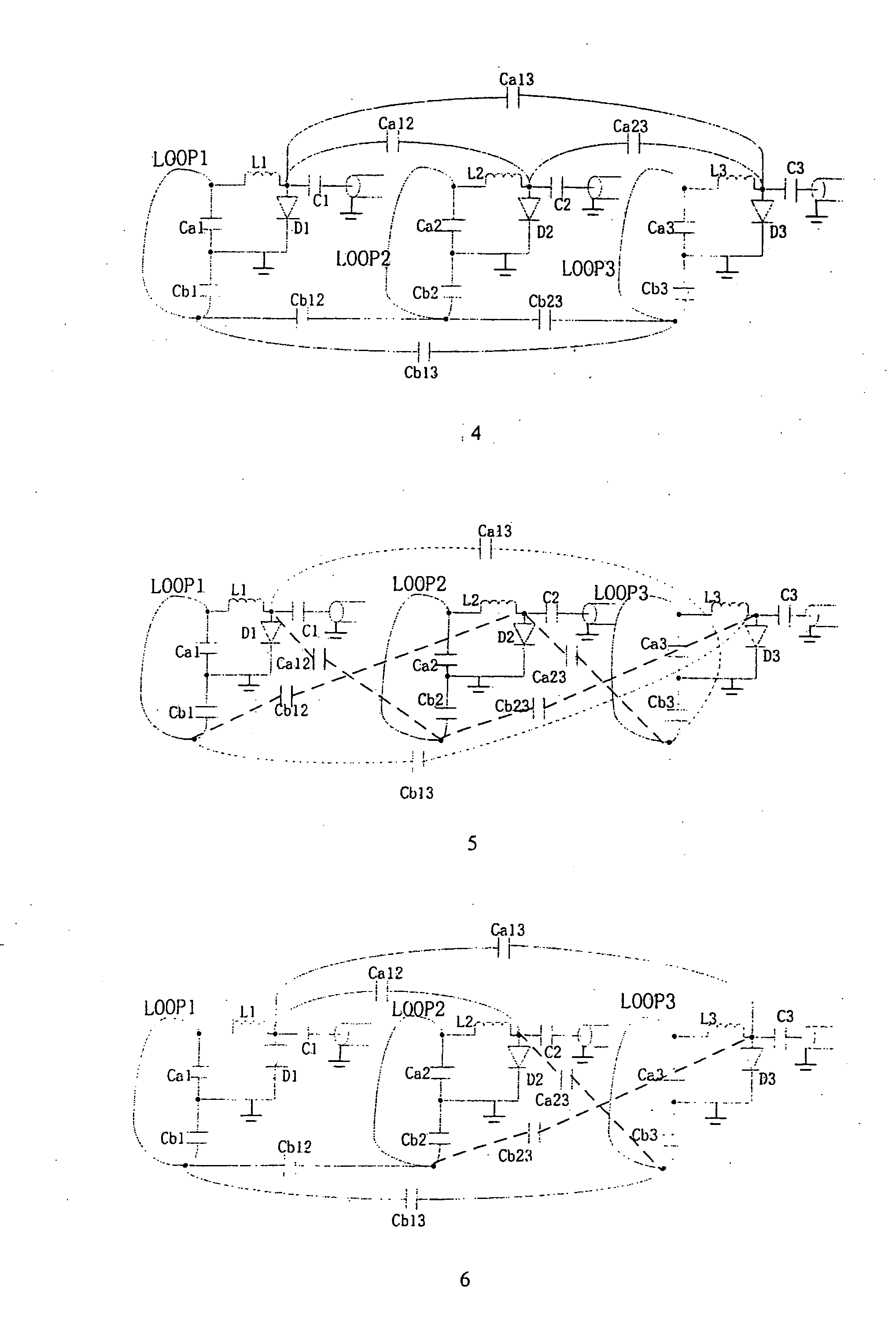
[0033]FIG. 4 shows the receiver coil array for a magnetic resonance receiving system in accordance with the present invention. The receiver coil array as shown has: three receiver coil circuits LOOP1, LOOP2, LOOP3 for receiving the magnetic resonance signals emitted from a human body, each of which, e.g. LOOP1, has a tuning circuit (Ca1, Cb1, L1), a detuning circuit (Ca1, L1, D1) and a matching circuit (Ca1, Cb1, L1, C1). The receiver coil array has a decoupling circuit in which a pair of decoupling capacitors are connected between each and every two of the receiver coil circuits for countering the coupling between the receiver coils. The decoupling circuit has two decoupling capacitors Ca12, Cb12 connected between the receiver coil circuits LOOP1 and LOOP2, two decoupling capacitors Ca23, Cb23 connected between the receiver coil circuits LOOP2 and LOOP3, and two decoupling capacitors Ca13, Cb13 connected between the receiver coil circuits LOOP1 and LOOP3. The decoupling capacitor C...

third embodiment

[0042]FIG. 6 shows an receiver coil array for a magnetic resonance receiving system in accordance with the present invention. In this embodiment, there are three pairs of decoupling capacitors between the three receiver coil circuits LOOP1, LOOP2, LOOP3, wherein the decoupling capacitors between LOOP1 and LOOP2 are Ca12 and Cb12, the decoupling capacitors between LOOP2 and LOOP3 are Ca23 and Cb23, and the decoupling capacitors between LOOP1 and LOOP3 are Ca13 and Cb13.

[0043] Parallel decoupling is used between LOOP1 and LOOP2, and the decoupling capacitor Ca12 has its both ends grounded respectively through the diodes D1, D2 in the detuning circuit of LOOP1, LOOP2, the decoupling capacitor Cb12 has its both ends grounded respectively through the tuning capacitors Cb1, Cb2 of LOOP1, LOOP2. Cross decoupling is used between LOOP2 and LOOP3, the decoupling capacitor Ca23 has one end grounded through the diode D2 in the detuning circuit of LOOP2, and the other end grounded through the tu...


PUM


Abstract

A receiver coil array for a magnetic resonance imaging system has multiple receiver coil loops that are decoupled from each the by a decoupling circuit that connects a pair of decoupling capacitors between any two of the receiver coil loops. One capacitor of each pair of decoupling capacitors has both ends grounded respectively through diodes of detuning circuits in the different receiver coil loops, and the other capacitor of each pair of decoupling capacitors has both ends grounded respectively through the tuning capacitors of different receiver coil loops. Alternatively the two decoupling capacitors in each pair have one end grounded through the diodes of respective detuning circuit, and the other end grounded through tuning capacitors of another said receiver coil loop.

Description

BACKGROUND OF THE INVENTION [0001] 1. Field of the Invention [0002] The present invention relates to a receiver coil array for a magnetic resonance imaging (MRI) system, particularly to a receiver coil array of an MRI system with a decoupling circuit. [0003] 2. Description of the Prior Art [0004] Magnetic resonance imaging (MRI) is an imaging modality, wherein the signals arising from the resonance of atomic nuclei within a magnetic field are reconstructed for imaging. More specifically, the basic principle of magnetic resonance is that for an atomic nucleus with an in odd number of protons, e.g. the hydrogen nucleus that is widespread in a human body, the positively charged protons thereof exhibit spinning movements that create a magnetic moment, serving as a small magnet. The arrangement of the self-spin axes of the small magnet normally is irregular. In a homogenous strong magnetic field, however, the self-spin axes of the small magnet will be rearranged depending on the directio...

Claims


Application Information

Patent Timeline
Patent Type & Authority Applications(United States)
IPC IPC(8): G01V3/00
CPCG01R33/365G01R33/3415
Inventor WANG, JIAN MINZHANG, BEI
Owner SIEMENS HEALTHCARE GMBH
Why Eureka
Try Eureka