Acoustic device

a technology of acoustic devices and bending waves, which is applied in the direction of transducer diaphragms, plane diaphragms, deaf-aid sets, etc., can solve the problem of not being able to efficiently radiate into acoustics, and achieve the effect of improving both the high frequency and low frequency limits of an audio devi

Inactive Publication Date: 2006-01-12
NEW TRANSDUCERS LTD
View PDF3 Cites 8 Cited by
  • Summary
  • Abstract
  • Description
  • Claims
  • Application Information

AI Technical Summary

Benefits of technology

[0044] The present invention thus provides a method to improve both the high frequency and low frequency limits of an audio device by relaxing the limits placed on motor design for conventional out of plane excitation.

Problems solved by technology

In other words a flat panel can carry mechanical sound energy but it cannot radiate into acoustics efficiently.

Method used


Image

  • Acoustic device
  • Acoustic device
  • Acoustic device

Examples


first embodiment

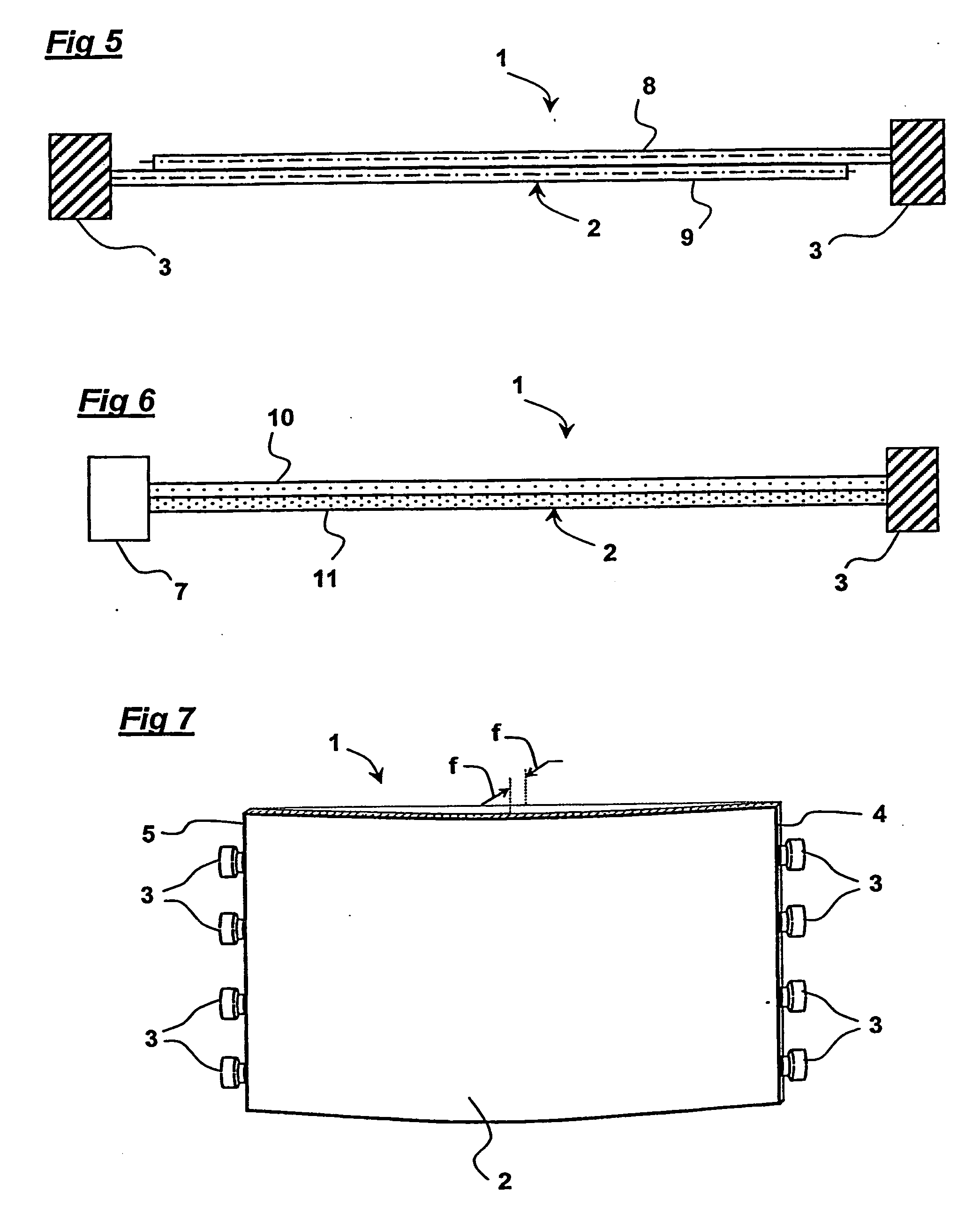
[0097]FIG. 7 is of loudspeaker 1 of the present invention comprising a rectangular panel radiator 2 convexly curved across its width and with a row of four exciters 3 coupled to the opposite ends 4,5 of the radiator. The panel material consists of a transparent monolithic material for operation as a flat panel loudspeaker to be placed in front of a display screen to produce a combined speaker and display.

[0098] The panel loudspeaker is intended to operate as a modal compression wave device at high frequencies and as a modal bending wave device at middle range audio frequencies. The in-plane method of excitation can also be designed to cause the panel to operate as a flexible whole body radiator at low frequencies. The three types of operation, compression, bending and whole body flexure combine to enable a loudspeaker of the present embodiment to cover a wide part of the whole audio frequency spectrum. In particular this embodiment gives a wider useful frequency range than a purely ...

second embodiment

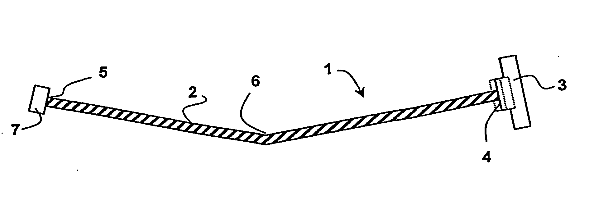
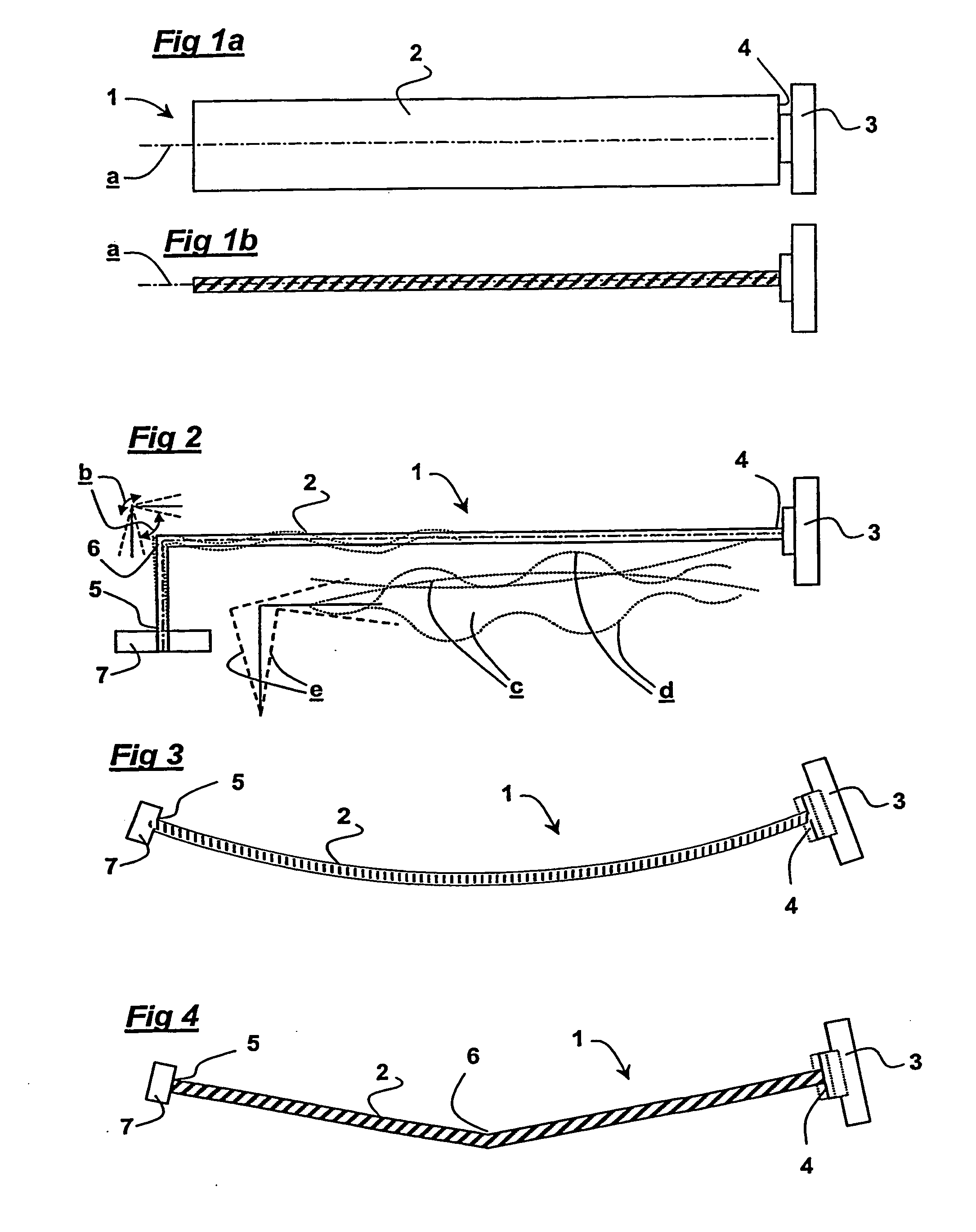
[0099] In loudspeaker 1 shown in FIGS. 8a and 8b a panel / speaker viewing screen can be flat which is a requirement for controlling optical reflection characteristics in some applications. When the panel radiator is driven in-plane by an exciter 3 the energy is converted into bending by the angled edge or corner 6 on the opposite side of the radiator. As the radiator moves in-plane the angle 6, which is mass loaded or simply supported against a chassis 12, rotates and imparts the energy back into the radiator as bending waves.

[0100] In a variation of the second embodiment shown in FIG. 8c two flat sections of panel 2 are joined by an open angle or by a short curve 6. The method may not be suitable for a view screen application because the angle 6 is in the central region of the panel where it would interfere with the transparency. The method lends itself to high aspect ratio designs in which the angle defines the exciter magnification in the same manner as the curve height in the emb...


PUM


Abstract

A bending wave loudspeaker comprising a panel-form radiator and an electromechanical vibration exciter coupled to the radiator, wherein the bending stiffness of the radiator is in the range 0.001 to 1000 Nm, wherein the coupling between the exciter and the radiator is such that a component of the applied energy results in compression waves in the radiator and wherein the radiator has a break in mid-plane symmetry resulting in acoustic radiation. A method of making a bending wave loudspeaker comprising selecting a panel-form radiator and an electromechanical vibration exciter, coupling the exciter to the radiator to have a relationship between the electromechanical impedance of the vibration exciter and the mechanical impedance of the radiator useful to the operating bandwidth of the radiator, arranging the bending stiffness of the radiator to be in the range 0.001 to 1000 Nm, arranging the coupling between the exciter and the radiator to be such that a component of the applied energy results in compression waves in the radiator and providing the radiator with a break in mid-plane symmetry to cause acoustic radiation.

Description

TECHNICAL FIELD [0001] This invention relates to acoustic devices and more particularly to bending wave acoustic devices, e.g. loudspeakers. Particularly this invention relates to methods and apparatus by which sound energy travelling through a solid body can be converted into out of plane motion that can radiate sound in air. The invention is thus applicable to resonant bending wave panel-form loudspeakers, e.g. of the kind described in WO97 / 09842. [0002] The invention particularly relates to a method of driving panel-form loudspeakers comprising driving the panel by an exciter along the plane of the panel, that is to say in compression. By the plane of the panel is meant a line running centrally between the large area surfaces of the panel through the section of the panel material, and will be referred to as “compression” drive. If the radiator panel were planar, i.e. flat, the material would move and vibrate but very little sound would be produced because there is very little res...

Claims


Application Information

Patent Timeline
Patent Type & Authority Applications(United States)
IPC IPC(8): H04R25/00H04R7/04
CPCH04R7/045
Inventor AZIMA, HENRYHILL, NICHOLAS PATRICK ROLANDMORECROFT, DENIS
Owner NEW TRANSDUCERS LTD
Why Eureka
Try Eureka