Trasmission device and adjustment method thereof
a transceiver and transceiver technology, applied in the field of transceivers, can solve the problems of inconvenient use, inability to adjust the device, and disadvantages of linear amplifiers, and achieve the effect of reducing the distortion of output signals
- Summary
- Abstract
- Description
- Claims
- Application Information
AI Technical Summary
Benefits of technology
Problems solved by technology
Method used
Image
Examples
first embodiment
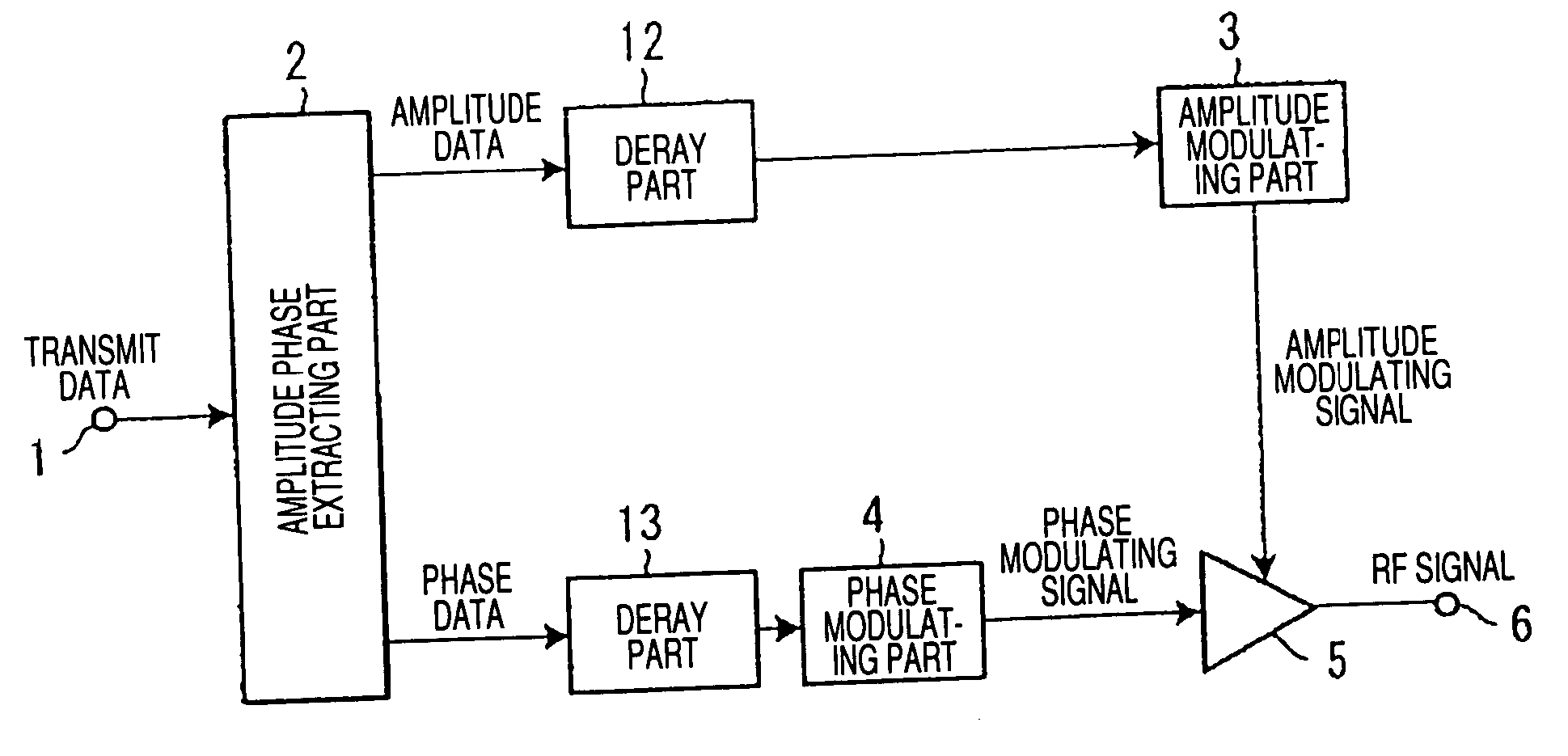
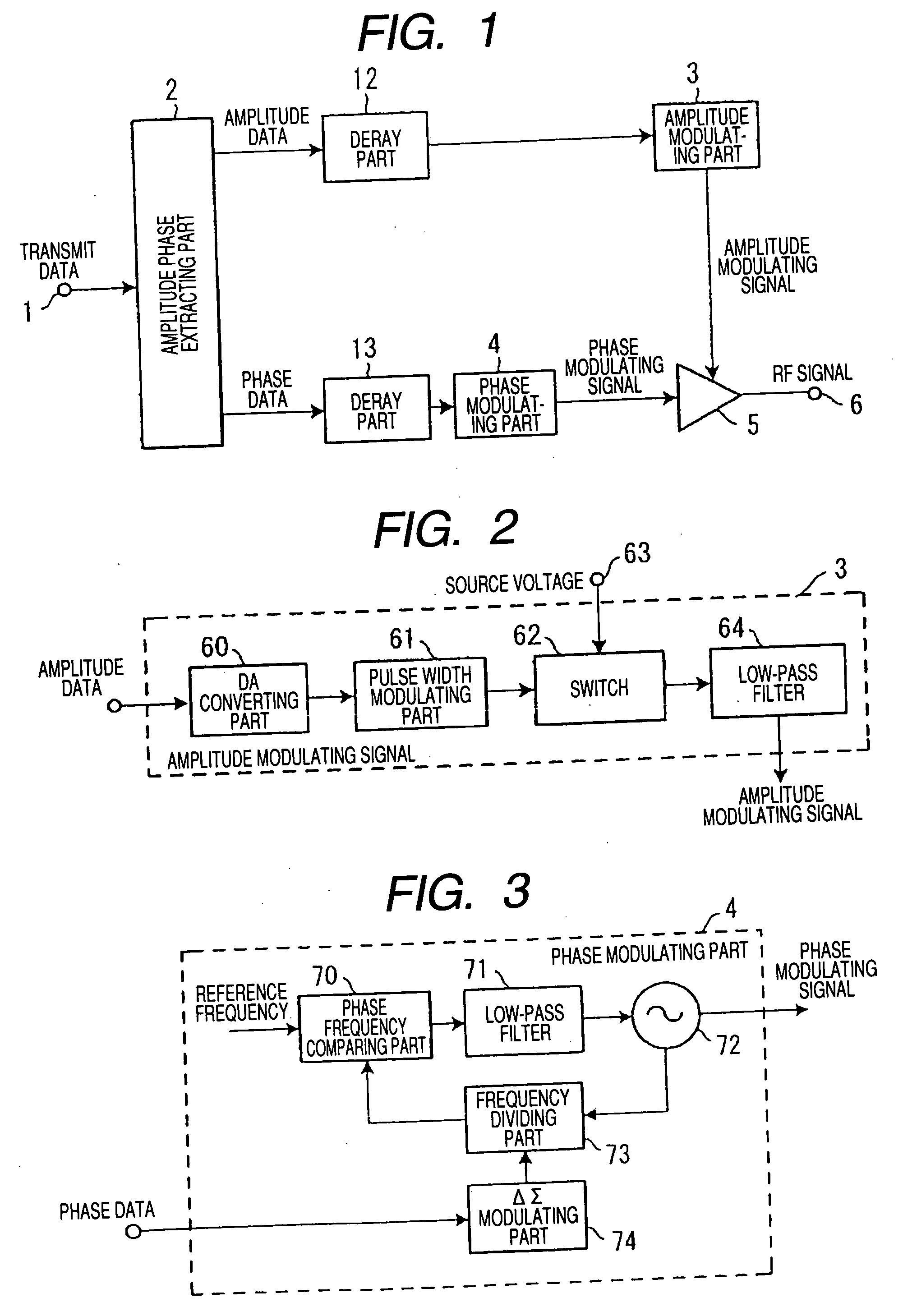
[0043]FIG. 1 is a block diagram showing the structure of main parts of a transmitter according to a first embodiment of the present invention.
[0044] The transmitter of the first embodiment comprises a transmit data input terminal 1, an amplitude phase extracting part (corresponding to an amplitude phase extracting unit) 2, an amplitude modulating part (corresponding to an amplitude modulating unit) 3, a phase modulating part (corresponding to a phase modulating unit) 4, a non-linear amplifying part (corresponding to a high frequency amplifying unit) 5, a transmit output terminal 6 and delay parts (corresponding to delay units) 12 and 13. The transmitter of this embodiment is characterized in that the delay part 12 is provided in a pre-stage of the amplitude modulating part 3 and the delay part 13 is provided in a pre-stage of the phase modulating part 4, respectively.
[0045] In a transmit data signal inputted from the transmit data input terminal 1, amplitude data and phase data ar...
second embodiment
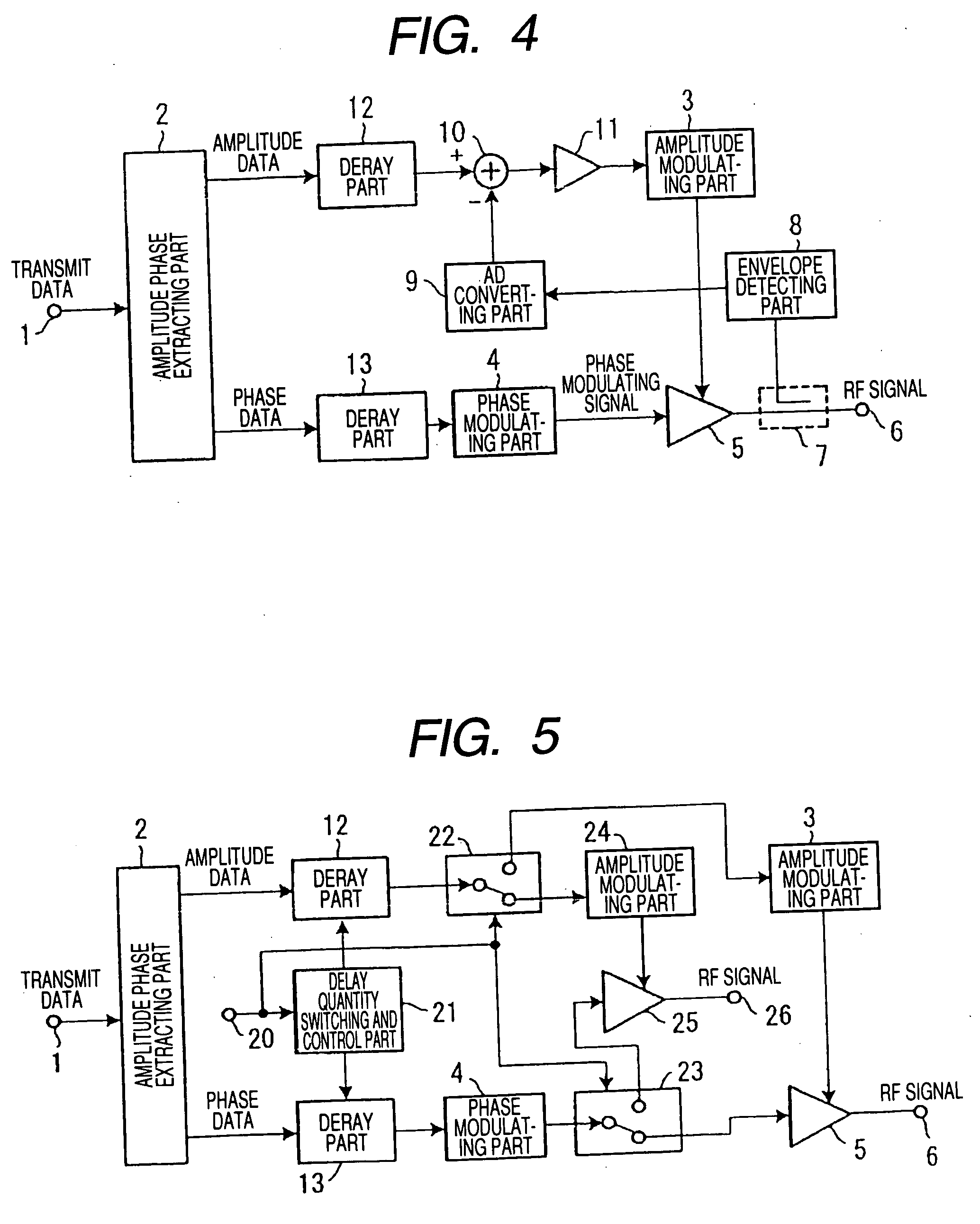
[0057]FIG. 4 is a block diagram showing the structure of main parts of a transmitter according to a second embodiment of the present invention.
[0058] The transmitter of the second embodiment includes a directional coupling part 7, an envelope detecting part (corresponding to an envelope detecting unit) 8, an AD converting part (analog-digital converting part) 9, an adding part 10 and an amplifying part 11 in addition to the structure of the first embodiment shown in FIG. 1. Other structures are the same as those of the first embodiment and the same components are designated by the same reference numerals and the explanation thereof is omitted.
[0059] In the second embodiment, an envelope component of an RF signal as the output of a non-linear amplifying part 5 is fed back in addition to the operation of the first embodiment. A part of a signal component of the output of the non-linear amplifying part 5 is allowed to branch by the directional coupling part 7 and inputted to the enve...
third embodiment
[0063]FIG. 5 is a block diagram showing the structure of main parts of a transmitter according to a third embodiment of the present invention.
[0064] The transmitter of the third embodiment includes a control signal input terminal 20 for inputting delay and signal path switching and control signals, a delay quantity switching and control part (corresponding to a delay quantity switching and control unit) 21, an amplitude data path switching part 22, a phase data path switching part 23, a second amplitude modulating part 24, a second non-linear amplifying art 25 and a second transmit output terminal 26 in addition to the structure of the first embodiment shown in FIG. 1. Other structures are the same as those of the first embodiment and the same components are designated by the same reference numerals and the explanation thereof is omitted.
[0065] In the third embodiment, a quantity of delay can be switched in addition to the operation of the first embodiment. The second amplitude mo...
PUM
 Abstract
Description
Claims
Application Information
 - R&D
- Intellectual Property
- Life Sciences
- Materials
- Tech Scout
- Unparalleled Data Quality
- Higher Quality Content
- 60% Fewer Hallucinations
Browse by: Latest US Patents, China's latest patents, Technical Efficacy Thesaurus, Application Domain, Technology Topic, Popular Technical Reports.
© 2025 PatSnap. All rights reserved.Legal|Privacy policy|Modern Slavery Act Transparency Statement|Sitemap|About US| Contact US: help@patsnap.com


