Method of converting energy

a technology of energy conversion and energy, applied in the direction of steam engine plants, machines/engines, mechanical equipment, etc., can solve the problems of affecting the performance of the system

Inactive Publication Date: 2006-01-19
SMITH & WESSON
View PDF16 Cites 63 Cited by
  • Summary
  • Abstract
  • Description
  • Claims
  • Application Information

AI Technical Summary

Benefits of technology

[0013] Heater 33 operates in FIG. 4 in the same manner as in FIG. 2 except that said second fluid temperature 17 must be greater than said working fluid temperature 5. Cooler 36 operates in FIG. 4 in the same manner as in FIG. 2 except that said third fluid temperature 21 must be less than said working fluid temperature 11. Cooler 37 and cooler 38 as seen in FIG. 3 may replace cooler 36 in FIG. 4 in the same manner as they replaced cooler 36 in FIG. 2 except that said fourth fluid temperature 21 must be less than said working fluid temperature 11.
[0014]FIG. 5 describes a further enhancement of the equipment arrangement described in FIG. 4. Said working fluid at pressure 65 leaves recuperator 31 at temperature 5; such temperature 5 being less than dew point temperature 6. Said working fluid at temperature 5 is directed into a first thermal side of pre-heater 32. Pre-heater 32 has said first thermal side separated from a second thermal side such that heat only is transferred between said first thermal side and said second thermal side. While passing through said first thermal side of pre-heater 32, said working fluid vaporizes to dew point 6 and possibly to a higher temperature. Said working fluid at pressure 65 and temperature 6 is then directed to said first thermal side of heater 33. Said first thermal side of heater 33 is segregated into two sections in series; a first section that heats said working fluid from temperature 6 to temperature 14 and a second section that heats said working fluid from temperature 15 to temperature 7. Said working fluid leaving said first section of said first thermal side of heater 33 is directed into said second thermal side of pre-heater 32. While passing through said second thermal side of pre-heater 32, said working fluid cools as a vapour to temperature 15. Said working fluid at pressure 65 and temperature 15 is then directed to said second section of said first thermal side of heater 33.

Problems solved by technology

Water has a tendency to erode, corrode and dissolve materials used in piping and equipment and contaminants accumulate in the re-circulating fluid.
Water has an affinity to absorbing air that greatly degrades the system performance.
Removing air is both an added equipment complexity and a parasitic energy load on the system.
Also since the specific volume of low-pressure steam is very large, the condensing equipment can grow to enormous sizes.
Consequently steam systems become uneconomical in smaller power output sizes and when the heat source temperature is low.
Such fluids are relatively expensive, flammable and environmentally sensitive.
Their lower enthalpy characteristics require greater pressure ratios that need multi-stage turbines and greater flow rates that negate some of the equipment size reduction benefits of the positive pressure at rejection temperature.
There are fewer suppliers and fewer knowledgeable operating and maintenance personnel available.

Method used


Image

  • Method of converting energy
  • Method of converting energy
  • Method of converting energy

Examples


Embodiment Construction

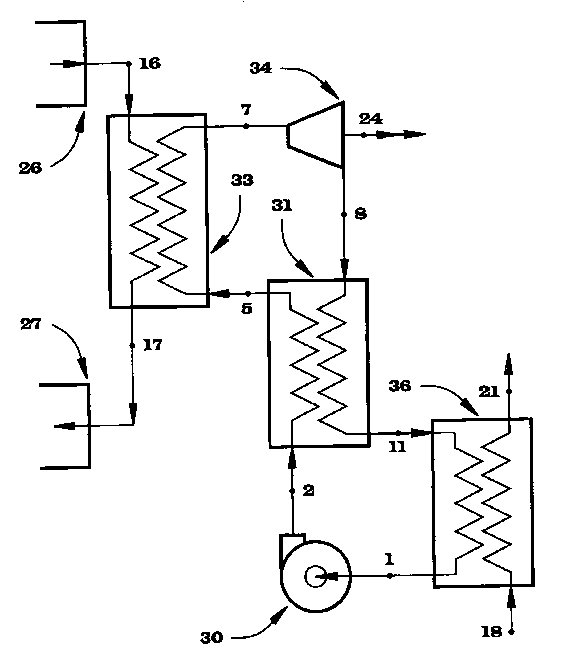
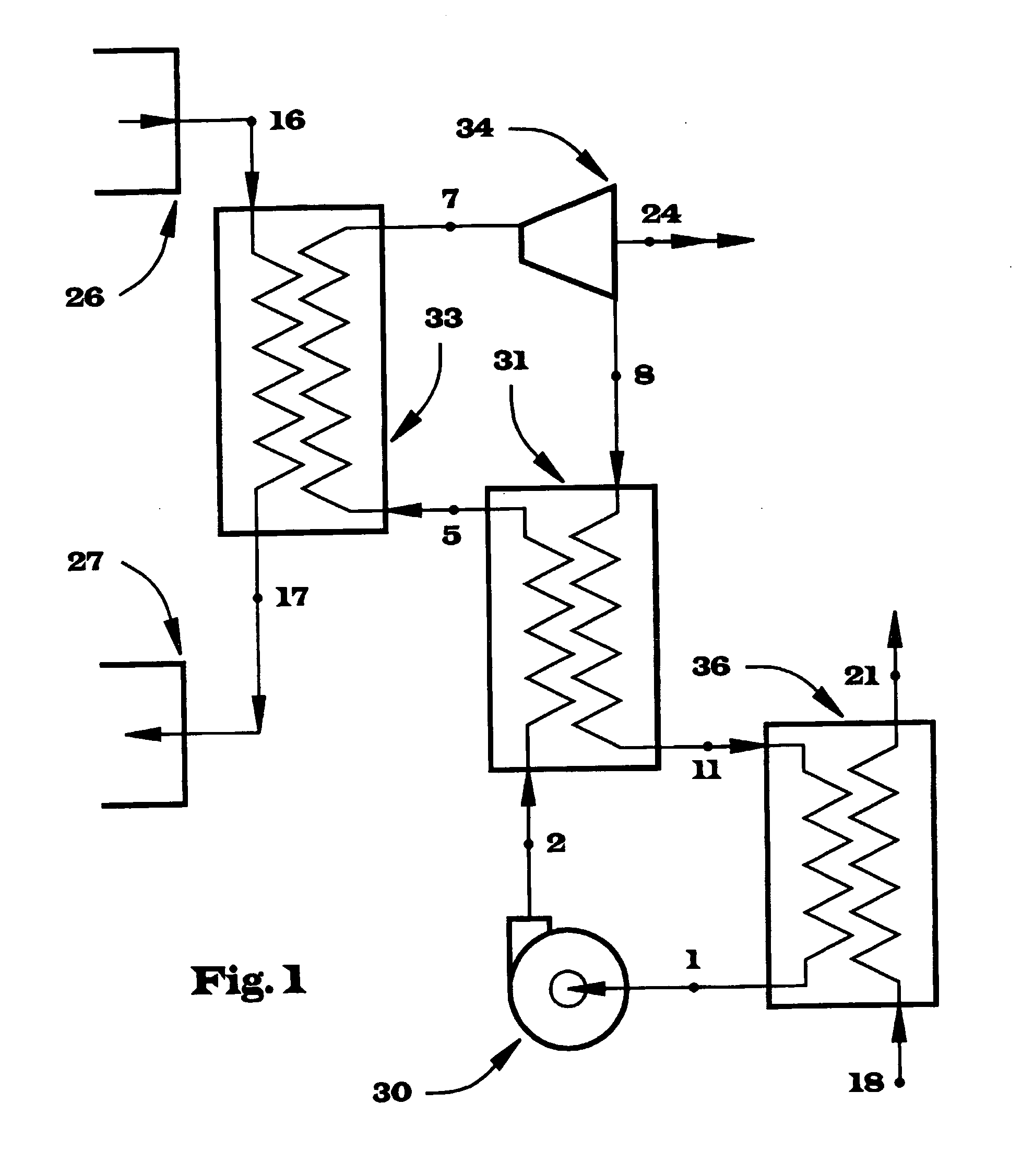
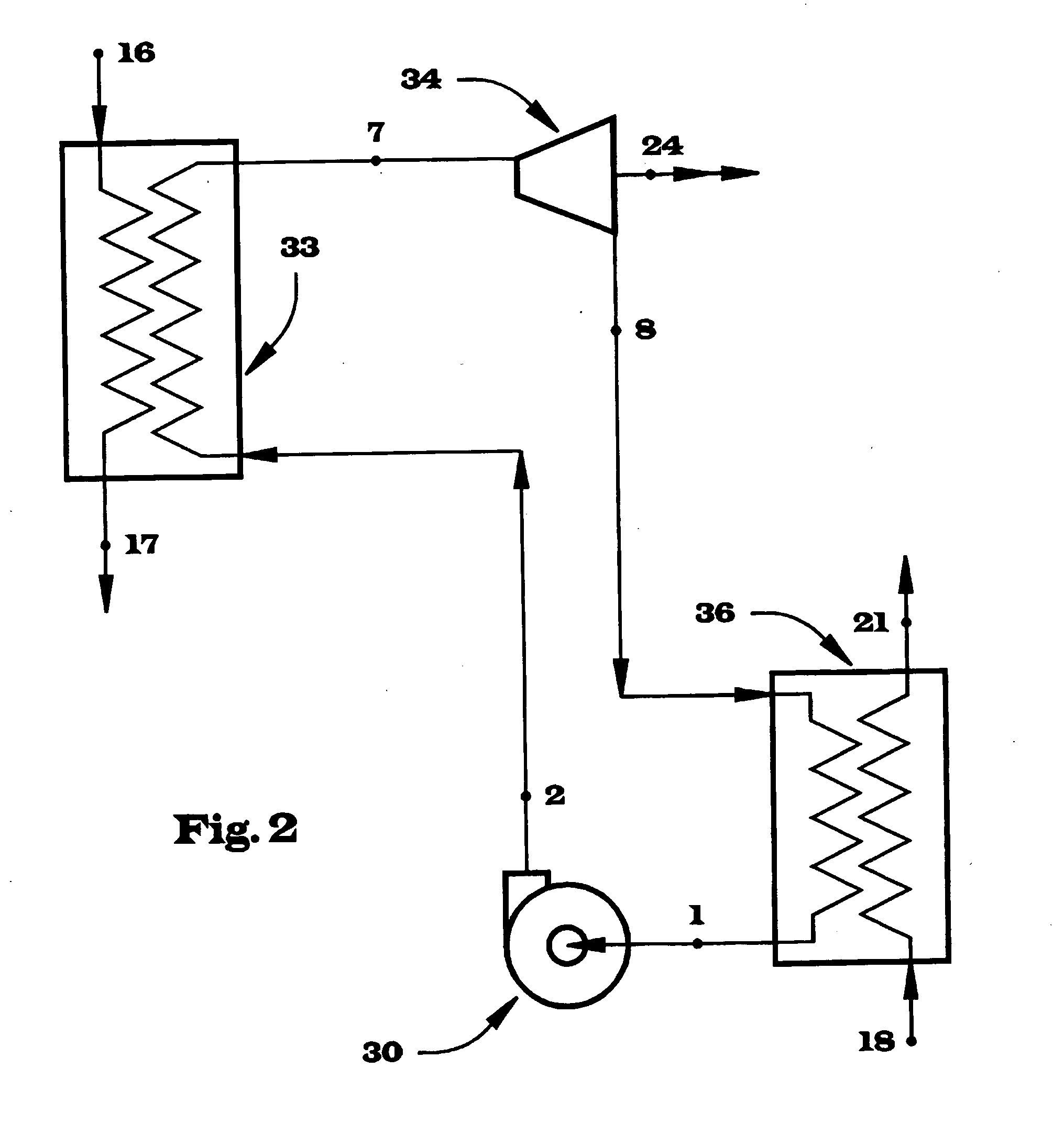
[0027] Selection of said working fluid is important for the practical application of the present invention. Although many multi-component fluids can be used as said working fluid, the preferred selection is a binary mixture of ammonia and water. Ammonia is a common industrial fluid, relatively inexpensive, readily mixes with water, not flammable, not a greenhouse gas and relatively environmentally benign. In high concentrations ammonia is a health hazard but it has the advantage of releasing a highly objectionable odour at very low concentrations, which serves to encourage early evacuation of a contaminated area FIG. 9 describes by way of example the temperature change across a two-phase region from bubble point 62 to dew point 64 at a constant pressure, as shown in FIG. 6, as it relates to the percent of ammonia in the mixture. The maximum change in temperature from bubble point 62 to dew point 64 approaches 170° F. at about 75% ammonia and exceeds 100° F. over a range from 30% amm...


PUM


Abstract

The invention provides a method of converting heat energy to a more usable form using a multi-component working fluid mixture that contains ammonia and water. The working fluid is operated in a thermodynamic cycle that includes liquid compression (30), vaporization (33), expansion through a turbine (34) and condensing (36). The multi-component fluid varies in temperature during phase change allowing for the use of counter-flow heat exchangers for the heater (33), cooler (36), recuperator and pre-heater (32). Significant recuperation is possible due to the temperature change during phase change. A pre-heater (32) can be applied to ensure only single-phase vapour exists within the heater. The invention can be used in conjunction with a biomass combustor or with waste flue gas from an existing industrial process. The coolant exits at a temperature sufficient to allow use in external heating applications or to minimize the size of external heat rejection equipment

Description

TECHNICAL FIELD [0001] Many industries produce wastes in the form of beat or biomass as a byproduct of their process. Environmental awareness has increased and effort is made to mitigate the consequences of these waste products. For instance, the cement industry produces particulate laden flue gases that must be cooled and cleaned before being released. In the forest industry it is undesirable to landfill biomass due to leaching but burning produces particulate in the flue gas that must be removed. Even though there are many installations that burn biomass without particulate removal systems, there is significant pressure for these practices to change. The useful recovery of heat from the flue gas of waste heat processes or biomass-fueled burners is usually determined to be uneconomical. Very large conversion plants may be economically justified only if they can locate sufficient biomass fuel within a reasonable transportation distance. [0002] The use of waste heat for beneficial pu...

Claims


Application Information

Patent Timeline
Patent Type & Authority Applications(United States)
IPC IPC(8): F01K13/00F01K23/04F01K23/06F01K25/06
CPCF01K25/06
Inventor SMITH, DOUGLAS WILBERT PAUL
Owner SMITH & WESSON
Why Eureka
Try Eureka