Discharging power source, sputtering power source, and sputtering device

a technology of sputtering power source and sputtering device, which is applied in the direction of electric variable regulation, process and machine control, instruments, etc., can solve the problems of reducing throughput of above method, excessive current vibration during operation at normal sputtering voltage,

Inactive Publication Date: 2006-01-19
SHIBAURA MECHATRONICS CORP
View PDF2 Cites 23 Cited by
  • Summary
  • Abstract
  • Description
  • Claims
  • Application Information

AI Technical Summary

Benefits of technology

[0037] The control unit may use the limit current value to which an offset is not added when the detection result by the voltage detection means is higher than a first predetermined voltage and use the limit current value to which an offset is added when t

Problems solved by technology

In various plasma application equipment, glow discharge application equipment and the like, occurrence of arc discharge during discharging often causes problems in the operation of the equipment.
This phenomenon is referred to as “splash”, which splashes particles of deposition material on the surface of the substrate 100, thus causing damage.
On the other hand, the above method (1) has a problem of decreasing throughput bec

Method used


Image

  • Discharging power source, sputtering power source, and sputtering device
  • Discharging power source, sputtering power source, and sputtering device
  • Discharging power source, sputtering power source, and sputtering device

Examples


example

[0125] A specific example of quenching arc discharge according to the invention will now be described with reference to an Example.

[0126]FIGS. 9 and 10 are a graphical diagram illustrating the operation of the discharging power supply of the invention. That is, these figures show waveforms in which vibrating current is generated by the vibrating current generation unit VCG and arc discharge, and then arc is quenched.

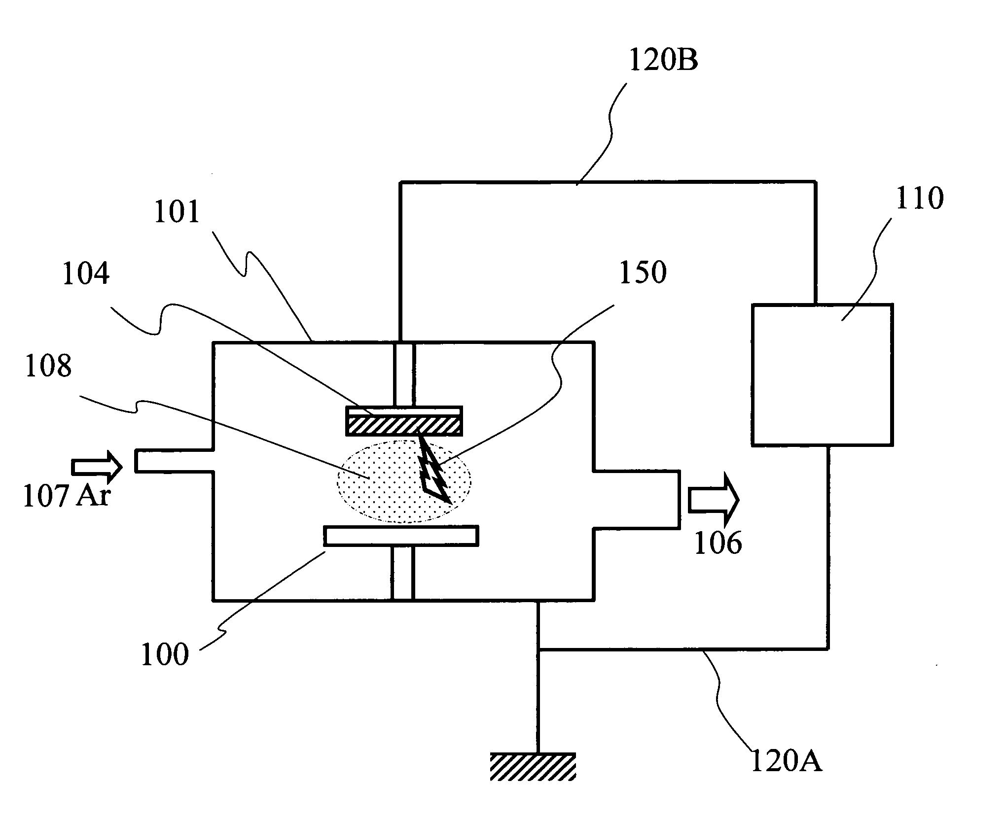
[0127] Here, in FIGS. 9 and 10, the horizontal axis represents time, which is classified into sputter state S, arc discharge state A, and resting state R. The waveform of FIG. 9 represents the voltage of the target 104, and the waveform of FIG. 10 represents the current of the target 104. Here, since the target voltage is measured at the target 104 relative to the chamber 101, the target voltage appears on the negative side relative to the position of symbol B (zero volt). The target current is represented on the positive side relative to the position of symbol C (zero...


PUM

PropertyMeasurementUnit
Electrical inductanceaaaaaaaaaa
Currentaaaaaaaaaa
Electric potential / voltageaaaaaaaaaa

Abstract

A discharging power supply according to the invention comprises: a direct current power supply unit; a control unit for controlling an output of the direct current power supply unit; and a vibrating current generation unit having a capacitance connected in parallel with a pair of outputs from the direct current power supply unit and an inductance connected to at least one of the pair of outputs, wherein the discharging power supply outputs discharging power via the vibrating current generation unit, the control unit controls the direct current power supply unit so that current outputted from the direct current power supply unit does not exceed a limit current value in at least a portion of a range of voltage that can be outputted from the direct current power supply unit, and the limit current value has a positive correlation with the absolute value of the voltage in the at least a portion of the range of voltage. According to this discharging power supply, regardless of whether the discharge power is set to be high or low, discharge current exceeding the limit characteristic line can be prevented from flowing. Even if arc discharge occurs, the amplitude of the vibrating current can be kept always larger than the discharge current. Thus the vibrating current definitely falls below zero ampere, and thereby arc can be definitely quenched.

Description

TECHNICAL FIELD [0001] The invention relates to a discharging power supply, sputtering power supply, and sputtering apparatus, and more particularly, to a discharging power supply and sputtering power supply having the capability of stable plasma discharge or glow discharge that can apply DC (direct current) voltage while preventing occurrence of arc discharge, and a sputtering apparatus using the same. BACKGROUND ART [0002] In various plasma application equipment, glow discharge application equipment and the like, occurrence of arc discharge during discharging often causes problems in the operation of the equipment. For this reason, a discharging power supply is often required that can definitely and quickly break arc discharge. In the following, as a specific example, a sputtering apparatus for use in forming thin film will be described. [0003]FIG. 11 is a schematic diagram showing the structure of a relevant part of a DC sputtering apparatus. This sputtering apparatus comprises a...

Claims


Application Information

Patent Timeline
IPC IPC(8): C23C14/00H01J37/34H02M3/337
CPCH01J37/34H02M3/3376H01J37/3444
Inventor KURIYAMA, NOBORUIMAGAWA, KAZUHIRO
Owner SHIBAURA MECHATRONICS CORP
Why Eureka
Try Eureka