Linear motor for use in machine tool

a linear motor and machine tool technology, applied in the direction of mechanical energy handling, dynamo-electric machines, electrical apparatus, etc., can solve the problems of reducing processing accuracy, limiting high-speed processing, and limiting speed at fast forward speed of 20 m/minute, so as to achieve high-accuracy processing, significantly reduce cogging force, and reduce processing speed

Inactive Publication Date: 2006-01-19
SHIN ETSU CHEM IND CO LTD
View PDF10 Cites 44 Cited by
  • Summary
  • Abstract
  • Description
  • Claims
  • Application Information

AI Technical Summary

Benefits of technology

[0019] According to the first aspect of the present invention, by disposing the magnetic cores (auxiliary cores) on both ends of the movers and by making the length of the magnetic cores shorter than that of the armature cores (main cores), the cogging force can be significantly reduced, and thus high-accuracy processing becomes possible. According to the second aspect of the present invention, by disposing the two mover blocks, each block having a length that is eight times longer than the stator magnet pitch and having nine teeth (armature cores) wound with the armature coils in the respective phases of three each, and by setting the spacing between the blocks to be ½ of the stator magnet pitch, the cogging force can be significantly reduced, and thus high-accuracy processing becomes possible.
[0020] According to the third aspect of the present invention, by disposing the three mover blocks, each block having a length that is eight times longer than the stator magnet pitch and having nine teeth (armature cores) wound with the armature coils in the respective phases of three each, and by setting the spacing between adjacent blocks to be ⅓ of the stator magnet pitch, the cogging force can be significantly reduced, and thus high-accuracy processing becomes possible.
[0021] According to the fourth aspect of the present invention, by disposing the three mover blocks, each block having a length that is eight times longer than the stator magnet pitch and having nine teeth (armature cores) wound with the armature coils in the respective phases of three each, the cogging force can be significantly reduced, and thus high-accuracy processing becomes possible.

Problems solved by technology

However, there have been limitations in high-speed processing, and the limit has been about 20 m / minute at fast forward speed.
Furthermore, in the cases of workpieces having a long length of more than 3 m, there has been a problem in that processing accuracy is reduced due to, for example, bending of the ball screw.
Therefore, a large force also works between the LM blocks 141 and the LM rails 142, so that the frictional force becomes very large, and thus there also has been a problem in that the lifetime of the guide is reduced.
As has been described with the laser processing machine in FIG. 10, the Y-axis direction driving device and the Z-axis direction driving device are mounted on the X-axis direction driving device, so that if the weight of the driving device is increased, then the thrust has to be increased to obtain the same acceleration, resulting in an increase in the size of the driving device.
If the cogging is large, then position control of the linear motor is not performed appropriately, and thus there has been a problem in that the processing accuracy of the laser processing machine deteriorates.

Method used


Image

  • Linear motor for use in machine tool
  • Linear motor for use in machine tool
  • Linear motor for use in machine tool

Examples


example 1

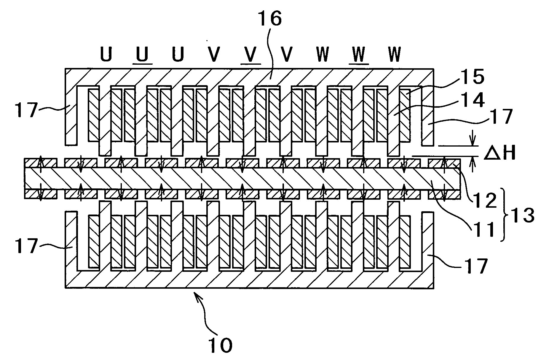
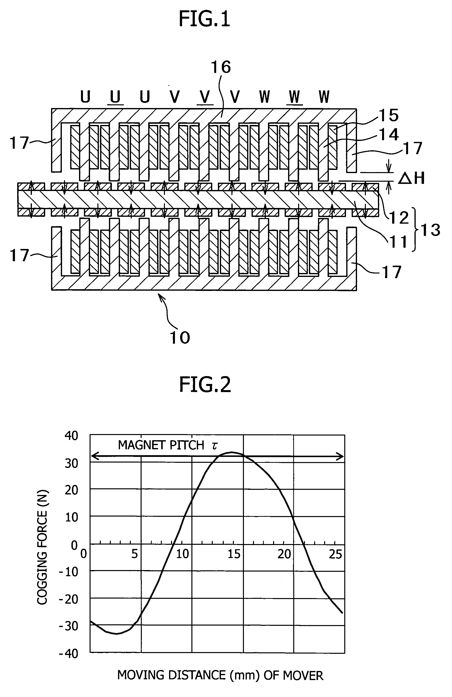
[0068] Auxiliary cores were provided as shown in FIG. 1, and the magnetic flux distribution was adjusted by changing the difference ΔH between the face of the auxiliary cores and that of main cores. A Nd—Fe—B based permanent magnet was used, and an iron yoke was used for the main cores and the auxiliary cores. Regarding the section sizes in FIG. 1, the width of the magnets was 18 mm, the thickness of the magnets in the magnetization direction was 5 mm, the magnet pitch was 25 mm, the width of the teeth of the armature cores was 10 mm, the length of the teeth was 34 mm, and the thickness of the stator yoke was 19 mm. The gap between the movers and the stator magnets was 1 mm. The movers and the stator had a thickness of 50 mm in the cross-sectional direction. It should be noted that the magnet pitch (τ) was the sum of the width of each of the permanent magnets and the gap distance between adjacent permanent magnets.

[0069]FIG. 9 shows the results. As shown in FIG. 9, as the differenc...

example 2

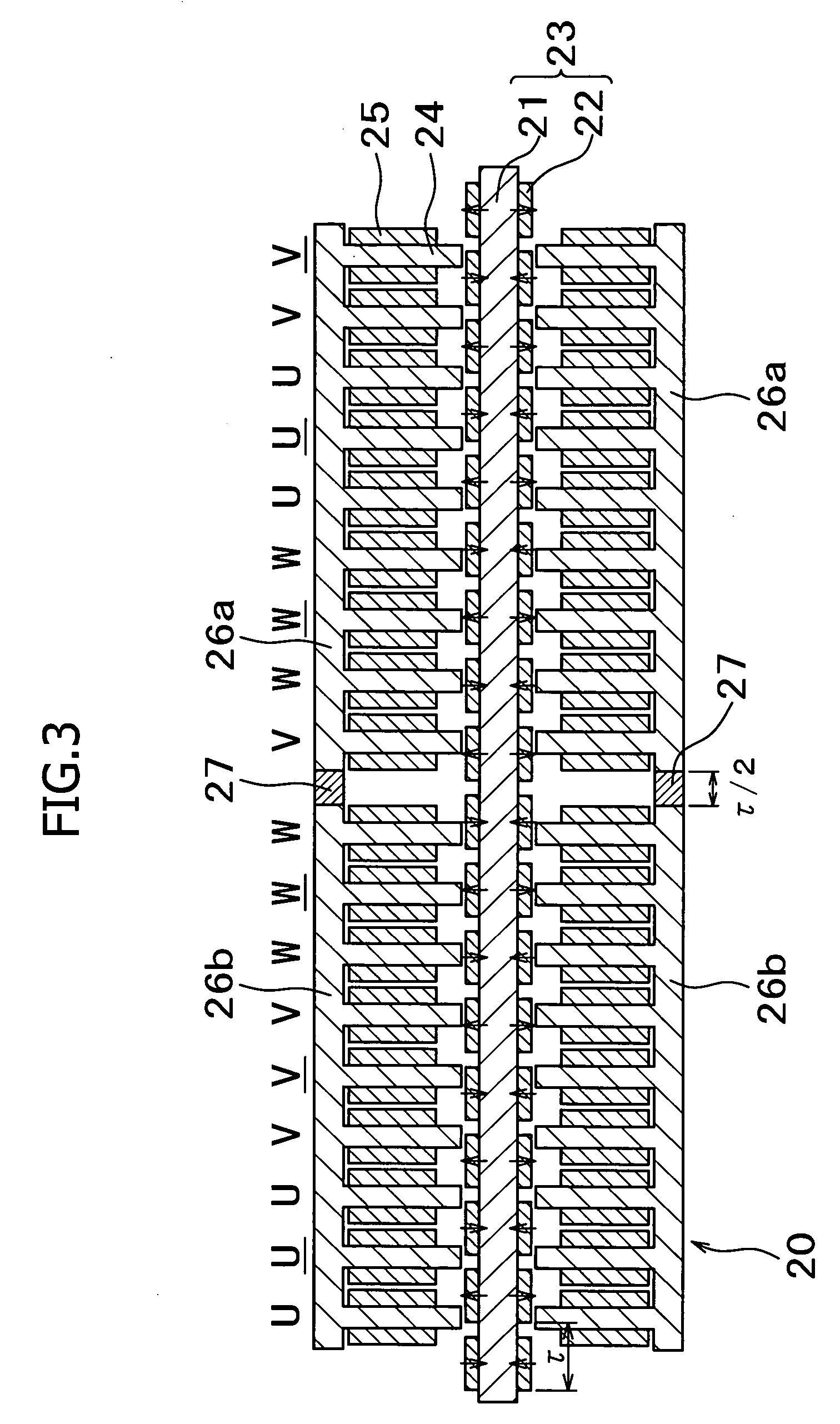
[0071] As shown in FIG. 3, a second mover block was disposed with a spacing that is ½ of the magnet pitch, which corresponded to 180° of the waveform of the cogging force. A Nd—Fe—B based permanent magnet was used, and an iron yoke was used as the core material. Here, regarding the section sizes in FIG. 3, the width of the magnets was 18 mm, the thickness of the magnets in the magnetization direction was 5 mm, the magnet pitch was 25 mm, the width of the teeth of the armature cores was 10 mm, the length of the teeth was 34 mm, and the thickness of the stator yoke (iron plate) was 19 mm. The gap between the movers and the stator magnets was 1 mm. The width of the spacer (non-magnetic stainless steel, SUS 304) between the first and second blocks was 12.5 mm. The movers and the stator had a thickness of 50 mm in the cross-sectional direction. It should be noted that the sizes in the conventional example in FIG. 14 are set to be the same as those in this example except that the mover an...

example 3

[0074] As shown in FIG. 5, second and third mover blocks were disposed with a spacing that is ⅓ of the magnet pitch, which corresponds to 120° of the waveform of the cogging force. A Nd—Fe—B based permanent magnet was used, and an iron yoke was used as the core material. Here, regarding the section sizes in FIG. 5, the width of the magnets was 18 mm, the thickness of the magnets in the magnetization direction was 5 mm, the magnet pitch was 25 mm, the width of the teeth of the armature cores was 10 mm, the length of the teeth was 34 mm, and the thickness of the stator yoke was 19 mm. The gap between the movers and the stator magnets was 1 mm. The width of the spacers (non-magnetic stainless steel, SUS 304) between the first and second blocks and between the second and third blocks was 8.33 mm. The movers and the stator had a thickness of 33 mm in the cross-sectional direction. It should be noted that the sizes in the conventional example in FIG. 14 are set to be the same as those in ...


PUM


Abstract

The invention is a linear motor that improves the processing speed of machine tools is also a linear motor with significantly reduced cogging force, with which high-speed and high-accuracy processing can be realized. More specifically, the invention is a linear motor for use in a machine tool comprising a stator in which a plurality of permanent magnets having the same shape are mounted on both faces of a plate-like yoke at even intervals such that the permanent magnets have polarities being perpendicular to a direction in which a pair of movers move and alternating in the moving direction; the movers in which armature cores wound with armature coils are disposed such that the armature cores are opposed to the rows of the permanent magnets on the both faces of the stator; and magnetic cores that are disposed on both ends of the movers such that the distance between the magnetic cores and the rows of the permanent magnets is longer than that between the armature cores and the rows of the permanent magnets. Moreover, provided is a laser processing machine in which the above-mentioned permanent magnet type linear motor is used for a three-dimensional moving mechanism.

Description

FIELD OF THE INVENTION [0001] The present invention relates to a permanent magnet type linear motor that is used broadly for the purpose of, for example, driving a moving part of a machine tool. DESCRIPTION OF THE RELATED ART [0002]FIG. 10 is a perspective view showing an example of a laser processing machine. There is a table 122 above a frame 121 shown in FIG. 10, and a workpiece (not shown) to be processed is placed on the table 122. Moreover, a driving device 123 that can move in the X-axis direction is mounted above the frame 121, and a driving device 124 that can move in the Y-axis direction is mounted to the X-axis direction driving device 123 via a fitting. A driving device 125 that can move in the Z-axis direction is mounted to the Y-axis direction driving device 124, and a torch 126 for emitting a laser beam is mounted to the Z-axis direction driving device 125. In FIG. 10, the wiring of the driving devices, a control device, and components for delivering the laser beam ar...

Claims


Application Information

Patent Timeline
Patent Type & Authority Applications(United States)
IPC IPC(8): H02K41/00
CPCH02K41/031H02K1/146H02K2213/03H02K7/09H02K1/2733
Inventor MIYATA, KOJIUCHIDA, MASANOBUOHASHI, KEN
Owner SHIN ETSU CHEM IND CO LTD
Why Eureka
Try Eureka