Reversible hydrogen storage systems
a hydrogen storage and reversed technology, applied in the direction of boron compounds, boron/diborane hydrides, chemistry apparatus and processes, etc., can solve the problems of inability to reversible the system, the system is not readily reversible, and the processing and storage equipment is relatively expensiv
- Summary
- Abstract
- Description
- Claims
- Application Information
AI Technical Summary
Benefits of technology
Problems solved by technology
Method used
Image
Examples
example 1
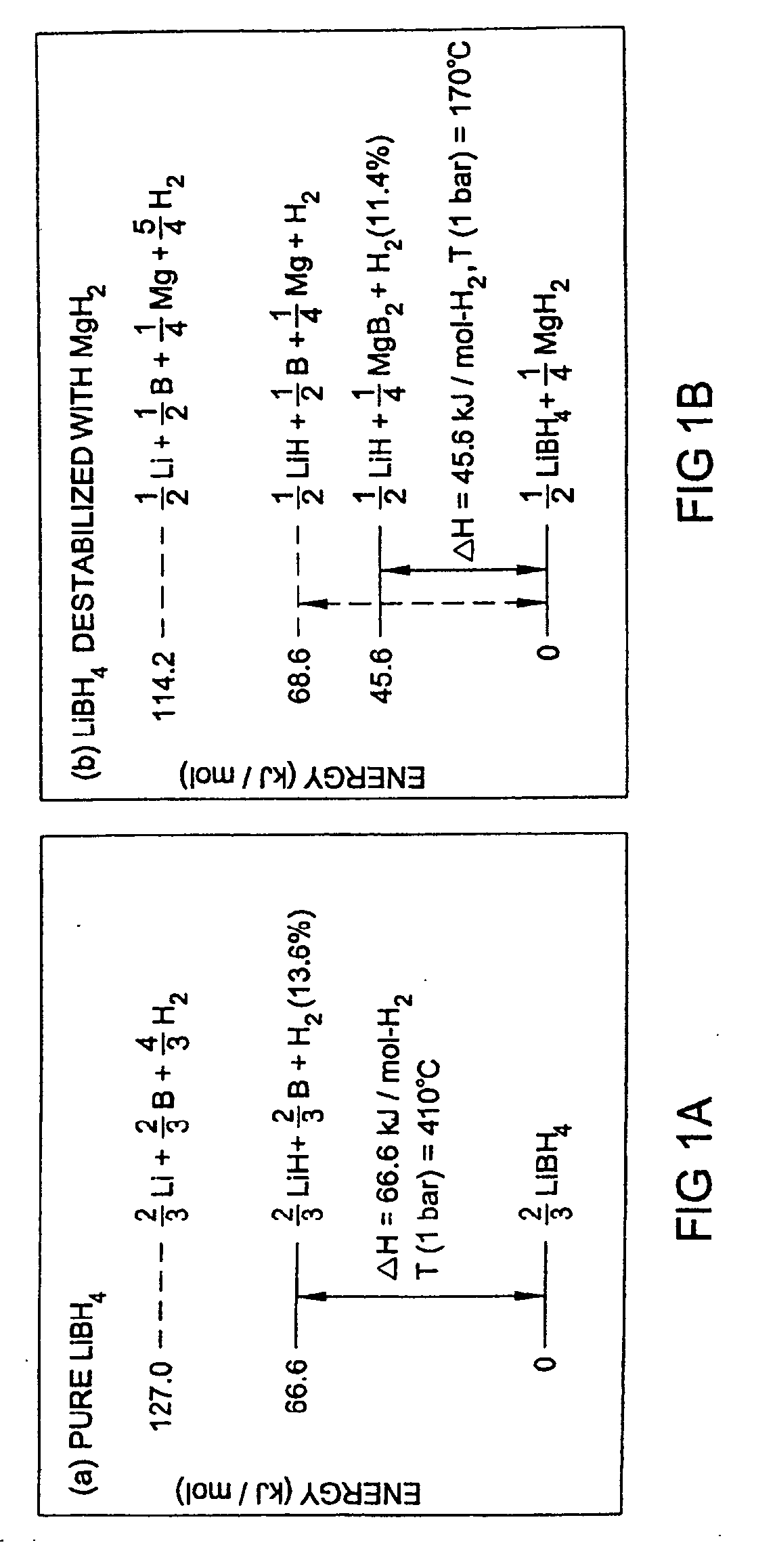
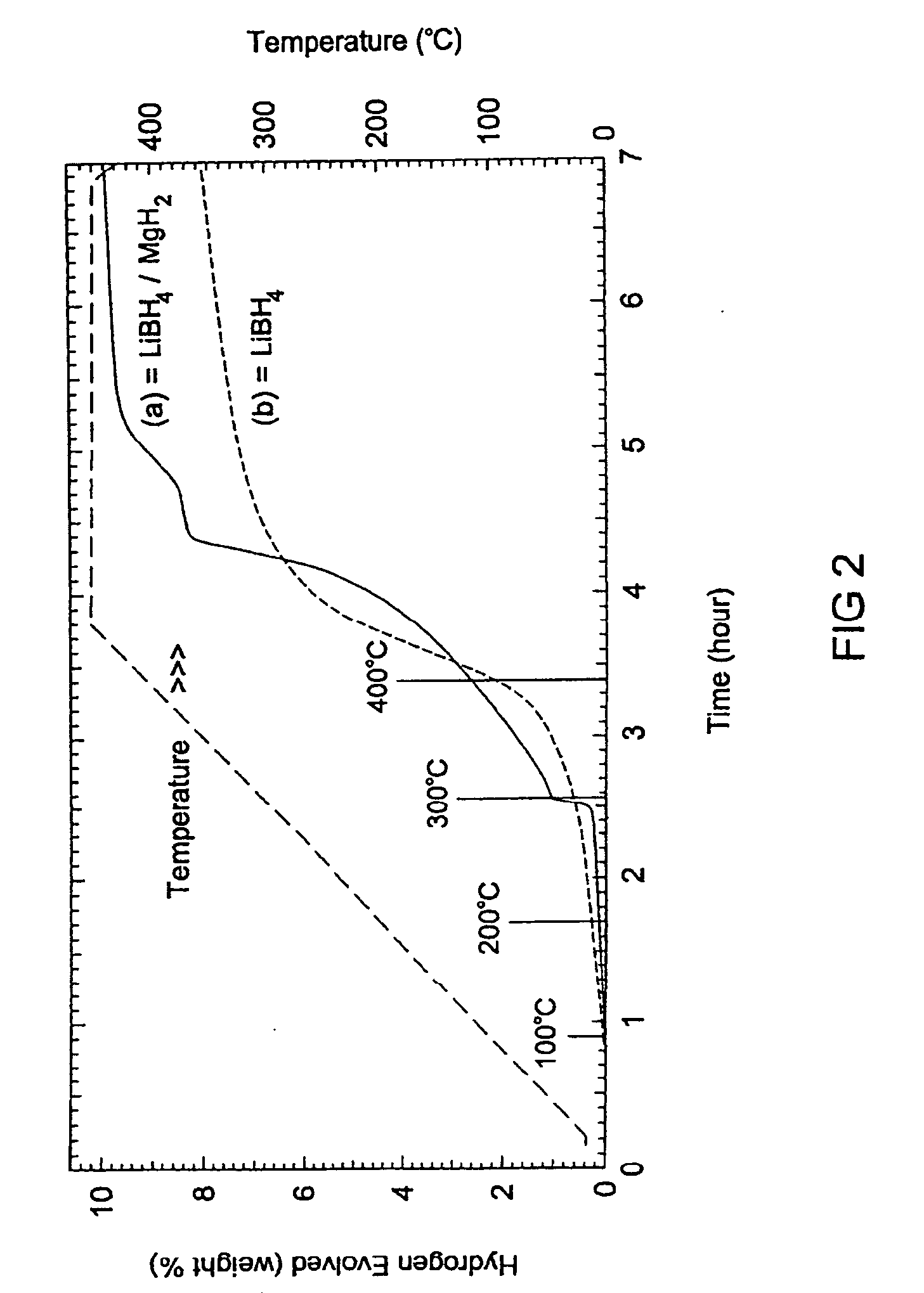
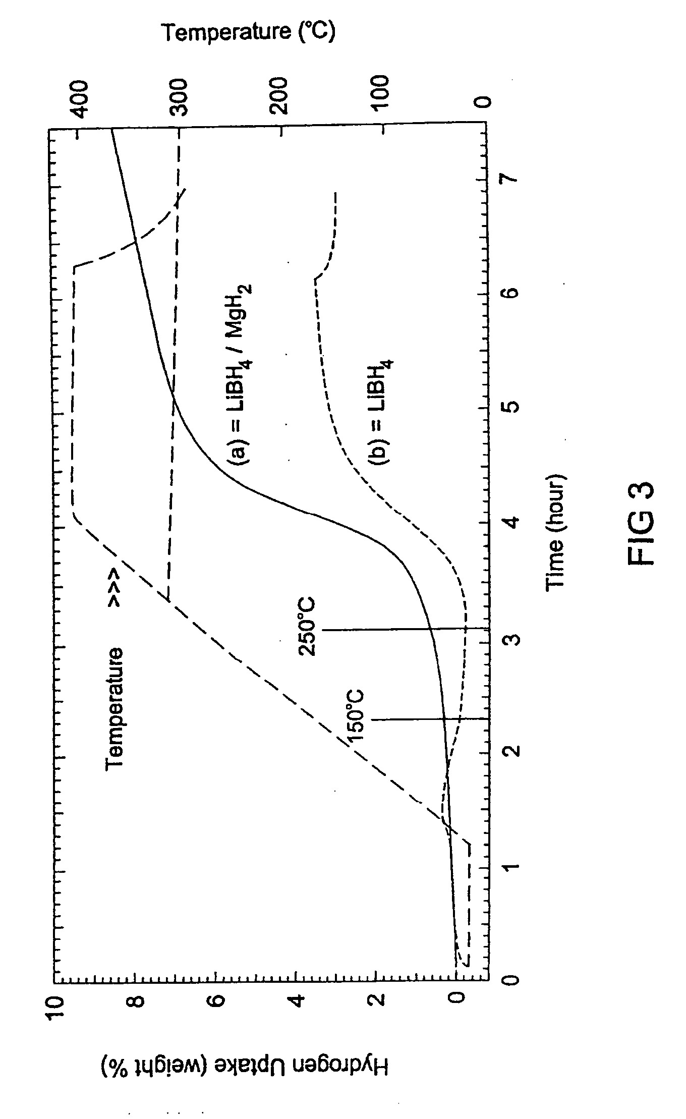
[0070] In a first experiment conducted according to a method of making a hydrogen storage compound according to one preferred embodiment of the present invention, a mixture of LiBH4 and MgH2 is prepared having a molar ratio of 2:1 that reacts according to the above described chemical reaction formula. The LiBH4 is commercially available from Lancaster Synthesis, Inc. of Windham, N.H. (and is specified to be ≧95% purity) and the MgH2 is commercially available at 95% purity from Gelest. The starting powders are mixed in the molar ratio 2LiBH4:1 MgH2 with 2 mole percent of a catalyst (TiCl3) added during milling. The starting materials weigh 1.2 grams and are added and sealed into a 80 cm3 hardened steel ball mill vessel under an argon (Ar) inert atmosphere. Thirty chrome-steel mill balls having a 7 mm diameter are placed in the vessel with the powder prior to sealing. The material is then high-energy ball milled for at least one hour in a Fritsch Pulversette 6 planetary mill at 400 rp...
example 2
[0074] In a second experiment, approximately 1.2 g mixtures of LiH+½MgB2 (the reaction products)+0.03 TiCl3 (catalyst) were mechanically milled for 1 hr as described previously in the first experiment.
[0075]FIG. 5 shows hydrogenation and dehydrogenation of a sample prepared in accordance with Example 2. The temperature ramp dehydrogenation / hydrogenation and isotherm measurements are performed in two custom Sieverts' apparatus. The system was pumped using an oilfree pumping station (the Tribodyn 100 / 120-HVP model available from Danielson Associates). The pressure at the sample is measured by replacing the sample container with an ionization gauge. After pumping overnight, a pressure of. 1×10⁻⁶ Torr (1.3×10⁻⁴ Pa) can be obtained. Hydrogen pressures are measured using low-range (0-100 psia or approximately 7.0×10² kPa) and high-range (0-3000 psia or approximately 2.1×10⁴ kPa) capacitance manometers at selected temperatures over the range from 75° to 575° C.
[0076] During heating at 2°...
example 3
[0082] In a third experiment, a mixture of LiBH4 and MgH2 is prepared having a molar ratio of 2:1 with a TiCl3 catalyst at 2 mole %, in the same manner as that described in Example 1 above. The ball-milled samples are dehydrogenated under two different atmospheric conditions to demonstrate the effect of hydrogen atmosphere on reaction products.
[0083]FIG. 8 shows x-ray diffraction (XRD) data for the two different dehydrogenation scenarios. Scan A shows an XRD for a material dehydrogenated by heating to 400° C. under flowing hydrogen at a pressure of 5 atm (approximately 500 kPa). Scan A shows that the reaction products include MgB2, but no detectable quantities of Mg metal were produced. The sample in Scan B was dehydrogenated by heating to 400° C. under a flowing argon atmosphere at 1 atm (100 kPa). The XRD pattern in Scan B shows that Mg metal was formed as a reaction product, but no detectable amounts of MgB2 are formed. As such, in certain embodiments of the present invention, w...
PUM
 Abstract
Description
Claims
Application Information
 - R&D
- Intellectual Property
- Life Sciences
- Materials
- Tech Scout
- Unparalleled Data Quality
- Higher Quality Content
- 60% Fewer Hallucinations
Browse by: Latest US Patents, China's latest patents, Technical Efficacy Thesaurus, Application Domain, Technology Topic, Popular Technical Reports.
© 2025 PatSnap. All rights reserved.Legal|Privacy policy|Modern Slavery Act Transparency Statement|Sitemap|About US| Contact US: help@patsnap.com


