Article including environmental barrier coating system, and method for making

a technology of environmental barrier and coating system, applied in the direction of superimposed coating process, machine/engine, natural mineral layered products, etc., can solve the problems of significant surface recession and mass loss of silicon-bearing materials, unacceptably high recession ra

Inactive Publication Date: 2006-01-19
GENERAL ELECTRIC CO
View PDF9 Cites 66 Cited by
  • Summary
  • Abstract
  • Description
  • Claims
  • Application Information

AI Technical Summary

Benefits of technology

[0005] Embodiments of the present invention are provided to address this and other needs. One embodiment is an article for use in a high temperature environment. The article comprises a substrate comprising silicon; a bondcoat comprising silicon, disposed over the substrate; an intermed

Problems solved by technology

However, the environments characteristic of these applications often contain water vapor, which at high temperatures is known to cause significant surface recession and mass loss in silicon

Method used


Image

  • Article including environmental barrier coating system, and method for making
  • Article including environmental barrier coating system, and method for making

Examples


example 1

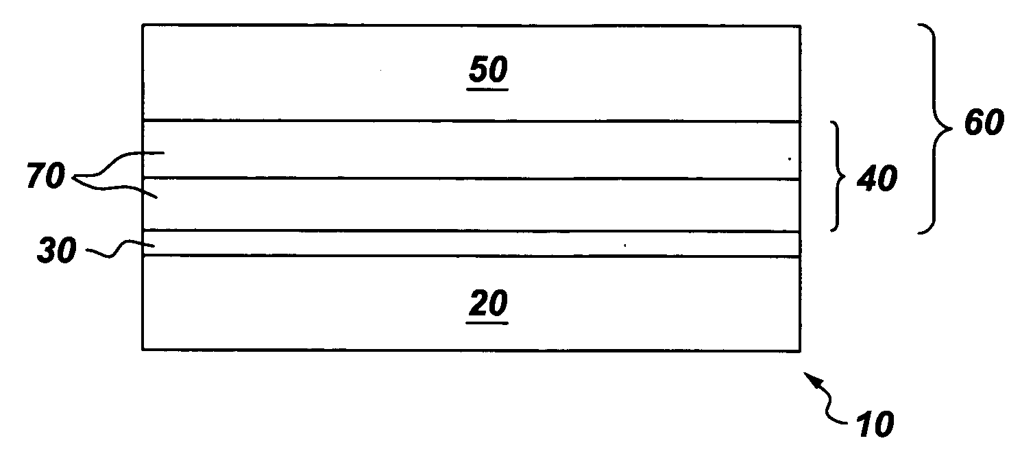
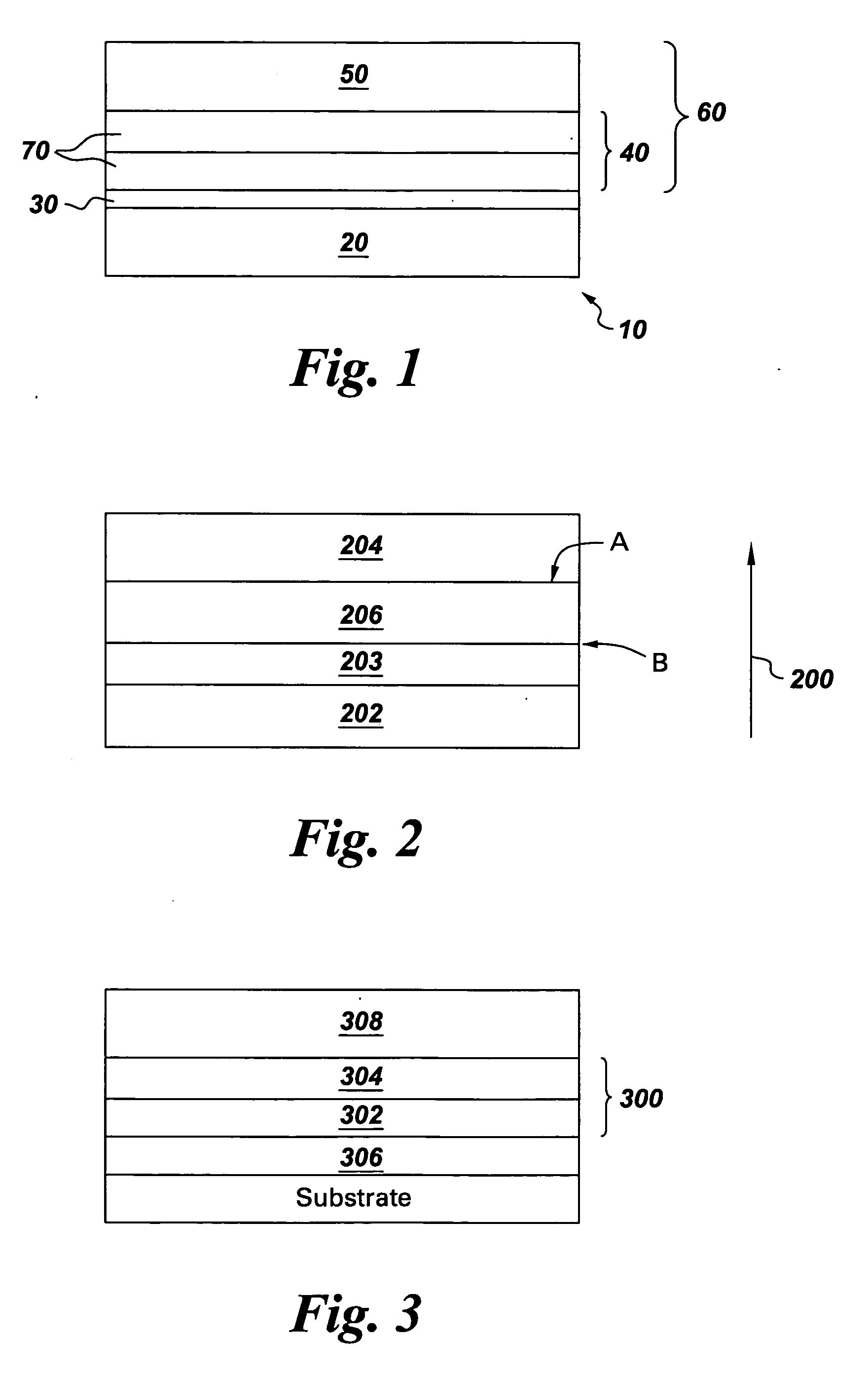
[0026] A coating system was applied to a SiC / SiC ceramic matrix composite (CMC) substrate by an air plasma spray technique. The CMC surface was prepared by grit-blasting with 36 grit SiC particles. First, a silicon bondcoat about 75 micrometers thick was applied to the substrate. Next, a yttrium disilicate (Y2Si2O7) intermediate barrier about 125 micrometers thick was deposited on top of the bondcoat. Finally, a top coat of yttrium monosilicate(Y2SiO5) 125 micrometers thick was deposited on the intermediate barrier. The coated substrate was heat treated for 10 hours at 1300 C in static air. X-ray diffraction showed the top coat consisted of crystalline yttrium monosilicate and the intermediate layer consisted of crystalline yttrium disilicate.

example 2

[0027] The coating deposition process described in Example 1 was followed with one modification. The intermediate layer in this example contained a mixture of yttrium monosilicate and yttrium disilicate. After exposure for 500 hours at 2400 F in air, an oxide layer was observed to have grown on the bond coat surface due to silicon oxidation. SEM / EDX analysis confirms the grown oxide layer was pure silica, SiO2. There was no evidence of chemical reaction between the silica layer and the intermediate layer, demonstrating excellent interlayer chemical compatibility.

example 3

[0028] Bulk pellets of barium strontium aluminosilicate (BSAS—a conventional EBC material), yttrium monosilicate, lutetium monosilicate, and ytterbium monosilicate were produced by cold pressing and sintering. The sintered samples were exposed to a water-vapor rich environment (90% H2O-10% O2 atmosphere) at 1315° C. for 100 hours. The BSAS samples lost weight due to interaction with steam and subsequent volatilization of silica in the form of gaseous silicon hydroxide. On the other hand, none of the rare earth monosilicate samples lost weight, suggesting that coatings made of these materials would show good stability in steam. XRD analysis revealed no loss of silica or rare earth oxide after steam exposure, confirming little, if any, reaction with steam.


PUM

PropertyMeasurementUnit
Temperatureaaaaaaaaaa

Abstract

Articles for use in a high temperature environment, and methods for protecting articles in such environments, are provided. The article comprises a substrate comprising silicon; a bondcoat comprising silicon, disposed over the substrate; an intermediate barrier disposed over the bondcoat, the barrier comprising at least one layer, wherein the at least one layer comprises a rare-earth silicate and is substantially free of mullite; and a topcoat disposed over the intermediate barrier, the topcoat comprising a rare-earth monosilicate. The method comprises providing a substrate, the substrate comprising silicon; disposing a bondcoat comprising silicon over the substrate; disposing an intermediate barrier over the bondcoat, the barrier comprising at least one layer, wherein the at least one layer comprises a rare-earth silicate and is substantially free of mullite; and disposing a topcoat over the intermediate barrier, the topcoat comprising a rare-earth monosilicate.

Description

BACKGROUND OF THE INVENTION [0001] This invention relates to high-temperature machine components. More particularly, this invention relates to coating systems for protecting machine components from exposure to high-temperature environments. This invention also relates to methods for protecting articles. [0002] Silicon-bearing materials, such as, for example, ceramics, alloys, and intermetallics, offer attractive properties for use in structures designed for service at high temperatures in such applications as gas turbine engines, heat exchangers, and internal combustion engines, for example. However, the environments characteristic of these applications often contain water vapor, which at high temperatures is known to cause significant surface recession and mass loss in silicon-bearing materials. The water vapor reacts with the structural material at high temperatures to form volatile silicon-containing species, often resulting in unacceptably high recession rates. [0003] Environmen...

Claims


Application Information

Patent Timeline
IPC IPC(8): B32B13/04
CPCC04B41/009C23C28/048C04B41/89F05B2230/90F05C2201/043F05C2203/06F05C2253/12C04B41/52C23C28/042C04B41/4527C04B41/5096C04B41/5024C04B2111/00405C04B35/565C04B35/584C04B35/806C04B35/58092
Inventor SAAK, JENNIFER SUMESCHTER, PETER JOELLUTHRA, KRISHAN LALSARRAFI-NOUR, REZADIDOMIZIO, RICHARD
Owner GENERAL ELECTRIC CO
Why Eureka
Try Eureka