
Method of programming a co-verification system

a co-verification system and programming method technology, applied in the field of coverification system, can solve the problems of requiring a lot of processing time to simulate ic behavior, and not providing sufficient assurance that the new and old portions of the design will properly work together

Active Publication Date: 2006-01-19
SYNOPSYS INC
View PDF5 Cites 92 Cited by
  • Summary
  • Abstract
  • Description
  • Claims
  • Application Information

AI Technical Summary

Benefits of technology

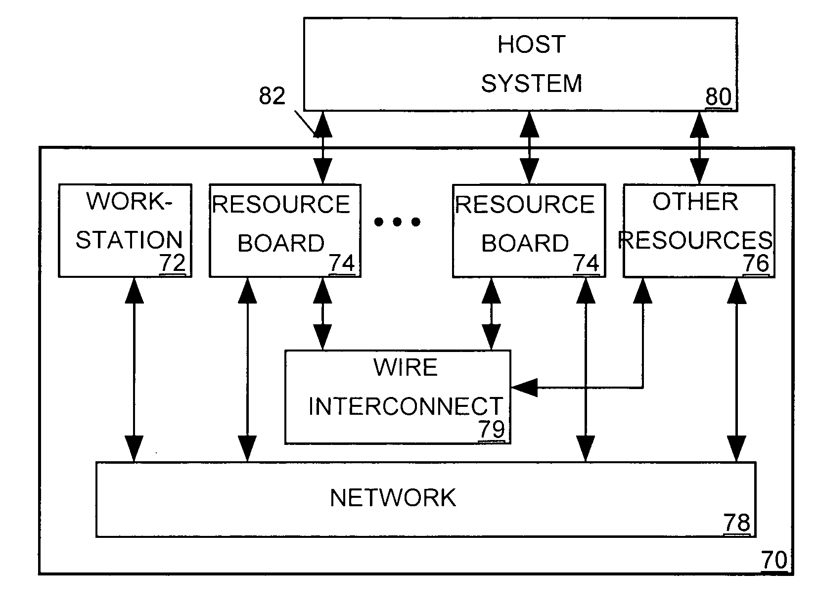
The invention is a system that allows a computer to simulate the behavior of an electronic device and have another device emulate it. The system uses a communication network to connect the computer and the emulation resources. The computer controls and monitors the emulation resources using data mapped to separate addresses in memory. The system also includes transactors that set and monitor the emulation signals. The technical effect of this invention is that it makes programming the simulator and emulator transparent to each other, making it easier to change the programming without affecting the other.

Problems solved by technology

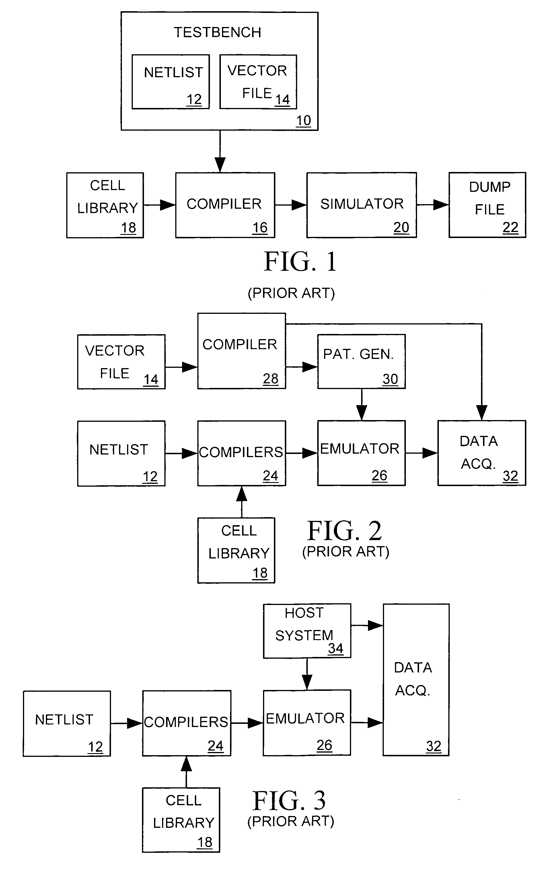
Although a simulator can predict the behavior of an IC based on either an RTL level or gate level netlist, it can require much processing time to simulate IC behavior.
To reduce processing time a designer can program a simulator to simulate only those portions of an IC design that are new or have been modified, but this approach may not provide sufficient assurance that the new and old portions of the design will properly work together.
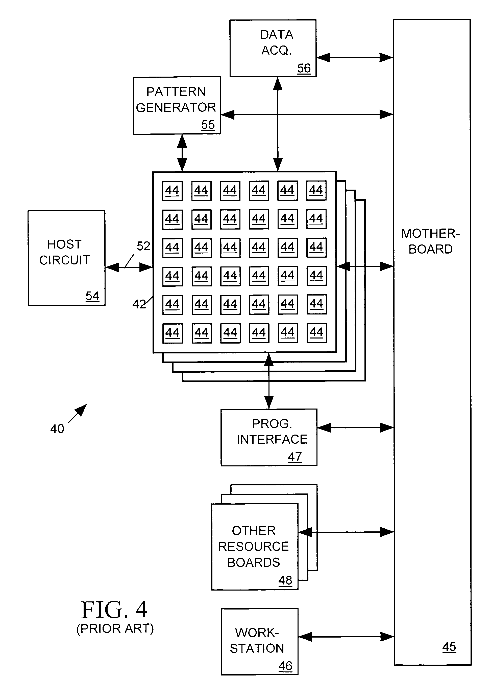
One drawback to the co-emulation system of FIG. 4 is that it is necessary to use separate compilers to compile programs for each system component, since workstation 46, pattern generator 55, data acquisition system 56 and devices on resource boards 48 include different memories and map signals to different memory space addresses.

Method used


Image

  • Method of programming a co-verification system
  • Method of programming a co-verification system
  • Method of programming a co-verification system

Examples


Embodiment Construction

[0040] The invention relates to a method of programming a co-verification system that can be implemented by a conventional computer reading and executing software residing on computer-readable media such as, for example, compact disks, floppy disks, hard disks, read only memory, and random access memory. While the drawings and this section of the specification describe a preferred embodiment of the method in accordance with the invention, the claims appended to this specification describe the full scope of the invention. The preferred embodiment of the invention described below illustrates one example of the invention recited in the claims. A programming system in accordance with the invention may be employed to program a co-verification system as described in detail in co-pending U.S. patent application Ser. No. 10 / 463,057, filed Jun. 16, 2003, incorporated herein by reference, and in co-pending U.S. patent application Ser. No. 10 / 735,342, also incorporated herein by reference.

[00...


PUM


Abstract

A co-verification system includes a computer programmed to act as a simulator for simulating behavior of a first portion of an electronic device under test (DUT) by acquiring, processing and generating data representing DUT signals. The co-verification system also includes emulation resources programmed to emulate a second portion of the DUT by receiving, processing and generating emulation signals representing DUT signals. The signals of the DUT are mapped to separate addresses within a memory space, and the simulator controls and reads states of emulation signals by writing data to and reading data from addresses of the memory space states mapped to the DUT signals the emulation signals represent. The computer and the emulation resources are also programmed to implement transactors communicating with one another through a packet routing network. The transactors set states of the emulation signals when the simulator writes to memory space addresses and for reading states of the emulation signals. The transactors monitor states of emulation signals and return data indicating those states to the simulator when the simulator reads memory space addresses mapped to DUT signals represented by the emulation signals.

Description

CROSS-REFERENCE TO RELATED APPLICATION [0001] This is a continuation-in-part of U.S. patent application Ser. No. 10 / 463,057, filed Jun. 16, 2003, a continuation-in-part of U.S. patent application Ser. No. 10 / 735,342, filed Dec. 11, 2003.BACKGROUND OF THE INVENTION [0002] 1. Field of the Invention [0003] The present invention relates to a co-verification system employing programmable logic devices and other resources for verifying the behavior of an electronic circuit described by a netlist, and in particular to a method of programming such a co-verification system. [0004] 2. Description of Related Art [0005] A typical digital integrated circuit (IC) employs register transfer logic (RTL) wherein each block of logic within the IC includes input and output registers for synchronizing state changes in its input and output signals to edges of a clock signal. Typically a designer will first generate an RTL level hardware description language (HDL) netlist employing Boolean expressions to ...

Claims


Application Information

Patent Timeline
Patent Type & Authority Applications(United States)
IPC IPC(8): G06F17/50
CPCG06F17/5027G06F30/331
Inventor WANG, MING YANGCHEN, DUAN-PINGSHEI, SWEY YANCHIU, HUNG CHUNNGUI, NEU CHOO
Owner SYNOPSYS INC
Learn More