Thin device and method of fabrication

a technology of thin film and manufacturing method, applied in piezoelectric/electrostrictive/magnetostrictive devices, piezoelectric/electrostriction/magnetostriction machines, impedence networks, etc., can solve the problems of time-consuming and labor-intensive operation

Inactive Publication Date: 2006-01-26
TOKO JAPANESE
View PDF25 Cites 42 Cited by
  • Summary
  • Abstract
  • Description
  • Claims
  • Application Information

AI Technical Summary

Benefits of technology

[0028] A further objective is to provide such an invention capable of producing FBAR devices with improved performance.

Problems solved by technology

This operation is tedious and time consuming.

Method used


Image

  • Thin device and method of fabrication
  • Thin device and method of fabrication
  • Thin device and method of fabrication

Examples


Embodiment Construction

[0035] The above described drawing figures illustrate the present invention in at least one of its preferred, best mode embodiments, which is further defined in detail in the following description. Those having ordinary skill in the art may be able to make alterations and modifications in the present invention without departing from its spirit and scope. Therefore, it must be understood that the illustrated embodiments have been set forth only for the purposes of example and that they should not be taken as limiting the invention as defined in the following.

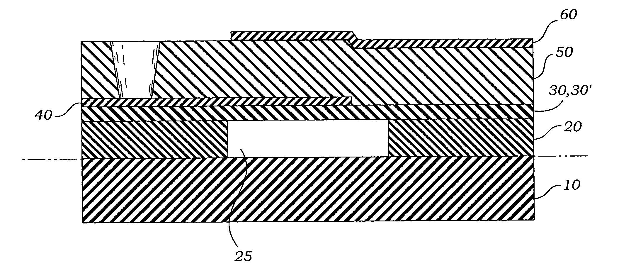
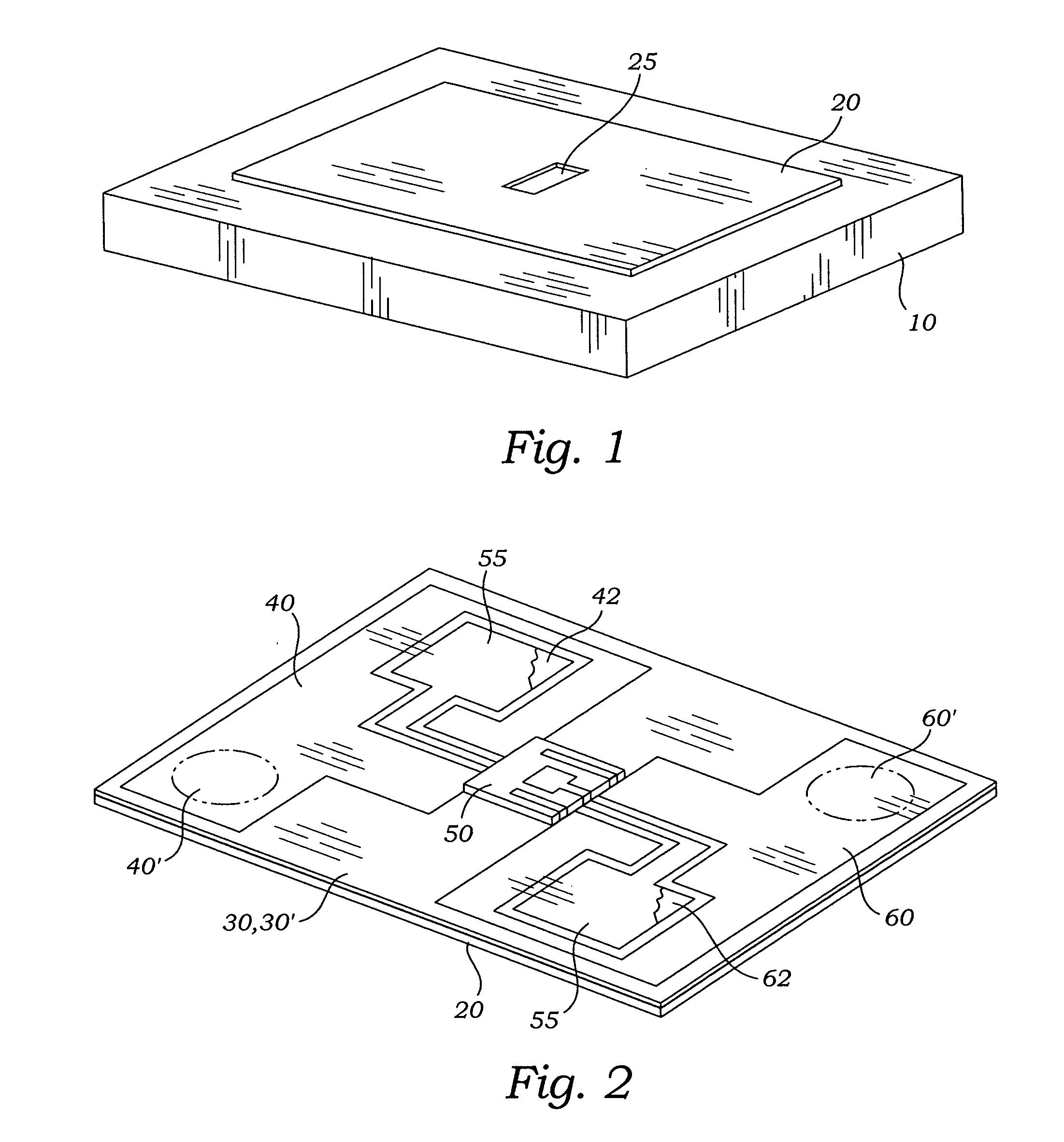
[0036] In one embodiment of the present invention, as shown in FIG. 1, a thermal oxide layer 20 of approximately 1.5 μm in thickness is grown on a silicon wafer substrate 10 having an exposed surface with a smoothness of about 0.3 μm RMS. The oxide layer 20 is patterned with a photoresist (not shown) and etched using standard photolithographic techniques in order to create a square or rectangular well 25 through the oxide layer ...


PUM

PropertyMeasurementUnit
heightaaaaaaaaaa
heightaaaaaaaaaa
smoothnessaaaaaaaaaa

Abstract

A method of fabricating air-bridge type FBAR devices provides for a piezoelectric material sandwiched between two electrodes with an air/crystal interface on each electrode to trap sound waves within the film structure. Copper is used as a sacrificial material deposited in cavities in the substrate. Following deposition of the electrodes and piezoelectric material, the copper is etched away leaving the bottom electrode suspended over a cavity void.

Description

BACKGROUND OF THE INVENTION INCORPORATION BY REFERENCE [0001] Applicant(s) hereby incorporate herein by reference, any and all U.S. patents and U.S. patent applications cited or referred to in this application. FIELD OF THE INVENTION [0002] This invention relates generally to thin film microdevices and method of manufacture, and more particularly to a thin film bulk acoustic resonator device having advantages in fabrication and operation. DESCRIPTION OF RELATED ART [0003] Acoustic resonators are used as filters for electronic circuits and there has been a continuing effort to provide reliable, inexpensive and compact devices. The basic structure consists of a sputtered piezoelectric film sandwiched between metal electrodes. The device is fabricated on an insulating substrate with bonding pads for electrode and ground plane connections. The devices are then tested and separated. The good devices are mounted and bonded into a package. The following art defines the present state of thi...

Claims


Application Information

Patent Timeline
Patent Type & Authority Applications(United States)
IPC IPC(8): H01L41/08
CPCH03H3/02H01L41/314H03H2003/021H03H9/173H10N30/074
Inventor TANIELIAN, ARAM
Owner TOKO JAPANESE
Why Eureka
Try Eureka