
Fluoroplastic composite elastomer

a fluoroplastic composite and elastomer technology, applied in the direction of machines/engines, synthetic resin layered products, packaging, etc., can solve the problems of affecting the flexural endurance of other pump types, such as progressive cavity pumps and centrifugal pumps, and damage to the process product and the internal workings of the pump, so as to improve the flexural endurance

Inactive Publication Date: 2006-01-26
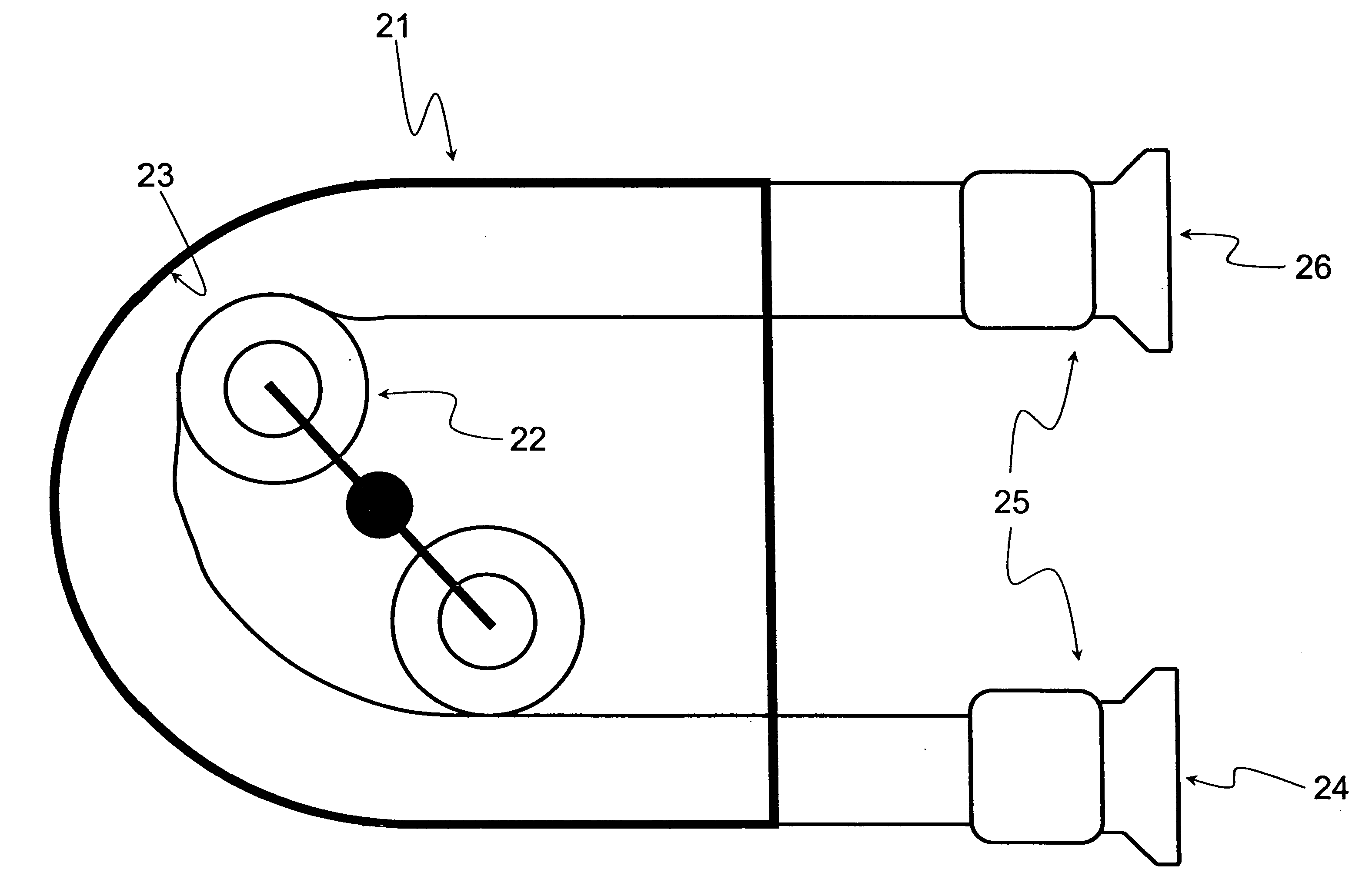
MAZTECH
View PDF8 Cites 39 Cited by
  • Summary
  • Abstract
  • Description
  • Claims
  • Application Information

AI Technical Summary

Benefits of technology

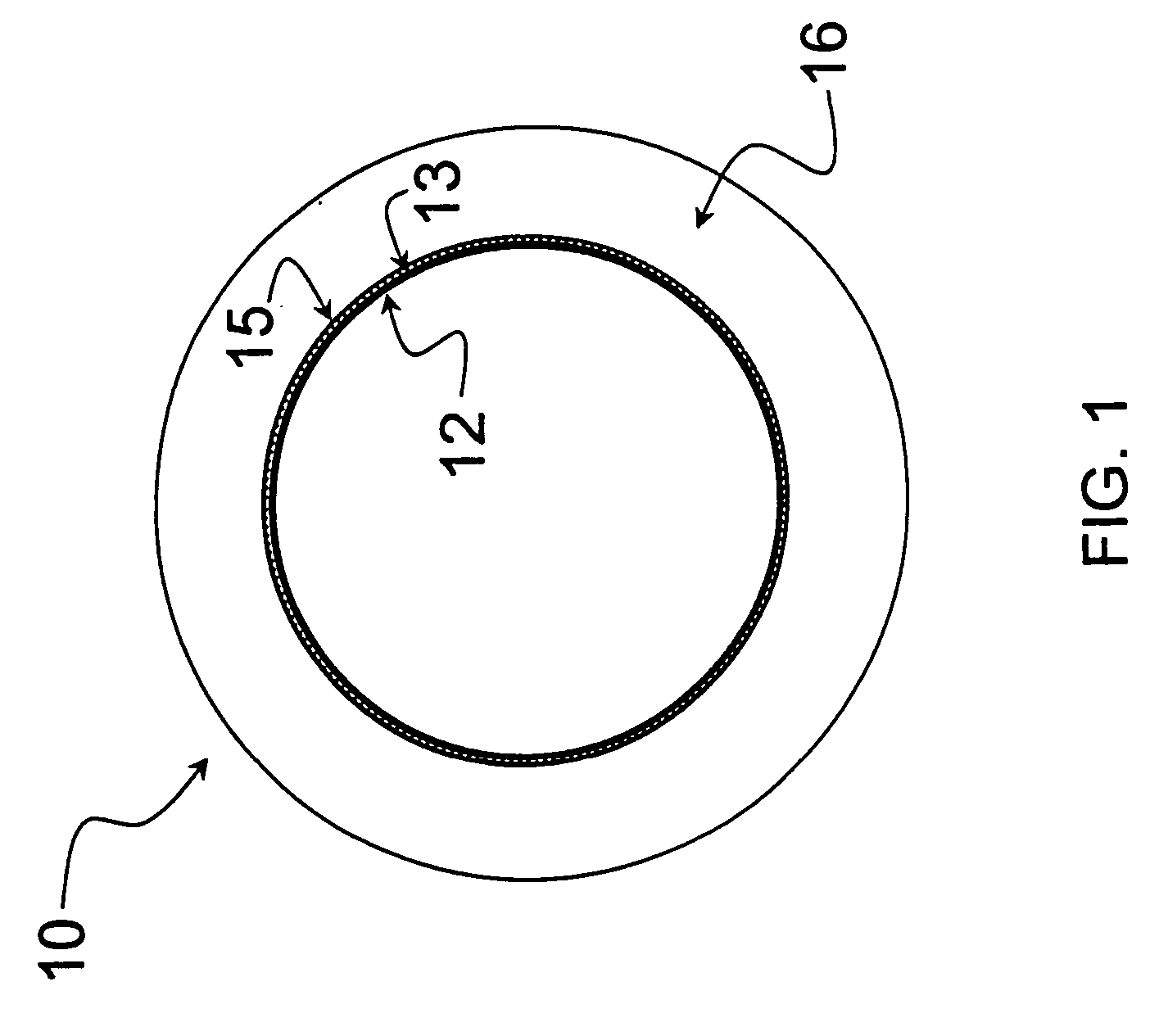
[0016] An objective of this invention is to provide a chemical resistant pump tube that utilizes a fluoroplastic liner and an elastomeric covering. Preferred liners are comprised of expanded PTFE and a melt processable fluoroplastic, such as PFA, FEP, PVDF or THV. The expanded PTFE structure provides improved flexure endurance while the fluoroplastic provides a means to adhere the many layers of fluoropolymers that are used to fabricate the pump tube liner. Adhesion is accomplished by sintering the fluoropolymer liner at a temperature necessary to melt the fluoropolymers into a monolithic unit that resists delamination. Single or multiple ply fluoroplastic films can be used to prepare the liner. Pump tubing can be fabricated in sizes ranging from 0.5 mm to 100 mm in inside diameter. Integral fittings can be molded or welded onto the ends of the inventive tubing for hygienic and chemical fluid handling. Fittings can be prepared from polypropylene, PFA, and other thermoplastic polymers as well as silicone and other thermoset polymers.
[0020] One additional objective of this invention is to demonstrate that either thermoset or thermoplastic covering materials can be rapidly bonded to the etched fluoroplastic liners. Utilizing previously extruded tubing as the covering by bonding them onto the liner with a tie-layer helps reduce the cost of fabrication.

Problems solved by technology

Centrifugal pumps, on the other hand, often have problems with damaging both the process product and the internal workings of the pump.
Other pump types, such as progressive cavity pumps and centrifugal pumps, are quickly damaged by operating without a fluid in the pumping chamber since they rely on the process fluid for lubrication.
Centrifugal pumps, on the other hand, are difficult to clean completely due to the many crevices in the pumping chamber.
The cleaning costs associated with centrifugal, air operated diaphragm, and progressive cavity pumps are significant and lead to considerable down-time.
Although peristaltic pumps have many advantages, they do suffer from some drawbacks.
In particular, pump tube materials are typically not compatible with aggressive chemicals.
Solvents can severely swell thermoset elastomers, such as silicone rubber and natural rubber.
Other chemicals result in chemical degradation of the polymeric tubing.
As a result, the application of peristaltic pumps in numerous industries has been limited.
Applications such as metering strong acids and bases, transferring solvent laden waste streams, transferring agrochemical compounds, dispensing printing inks, metering reactors with active pharmaceutical intermediates, and the recovery of hazardous materials have all been hampered without the availability of a chemical resistant tube and hose.
PTFE possesses excellent chemical resistance; however, it exhibits poor flexure endurance when it has not been stretched and expanded into a highly oriented structure as demonstrated by the instant invention.
The porous PTFE is useful in many applications requiring breathability, strength, and flex endurance; however, it is not suitable for containing process fluids due to its porosity.
This process is not economically viable for the production of peristaltic pump tube liners due to the cost of the disposable vacuum bags and the operation of the autoclave.
Commercially available tubes from Barnant Company are limited to 4 mm in inside diameter, thus restricting the range of achievable flow rates.
Those skilled in the art recognize that larger bore to wall ratio tubes have difficulty restituting without the aid of an elastomeric covering due to the plastic deformation and creep inherent in thermoplastic fluoropolymers.

Method used


Image

  • Fluoroplastic composite elastomer
  • Fluoroplastic composite elastomer
  • Fluoroplastic composite elastomer

Examples


example 1

25×4.8 mm Tube

[0034] A film of expanded PTFE-PFA was obtained from W. L. Gore & Associates, Inc. (Newark, Del.) as designated by the part number (5815060). The film had a density of 2.185 g / ml and a thickness of 0.020 mm. The 56 cm wide film was wrapped 13 times around a cylindrical metal mandrel having an OD of 25.4 mm and was heated for 60 min at 371° C. The resultant monolythic tube liner was removed from the mandrel and etched with a sodium ammonia solution. The resultant etched tube was placed back onto a metal mandrel and wrapped with a 0.2 mm thick adhesive tie-layer from Advanced Elastomers (8291-65TB) and was heated at 125° C. for 15 minutes. Next, the cooled liner was covered with a length of extruded Santoprene™ tubing obtained from Watson-Marlow Bredel (part number 903.0254.048). The article was wrapped with a nylon cure wrap to compress the composite and eliminate air entrapment. The mandrel was heated to a temperature of 175° C. for a period of 60 minutes to bond the ...

example 2

6.4 mm Tube with Water vs. Solvent

[0044] A film of expanded PTFE-PFA was obtained from W. L. Gore & Associates, Inc. (Newark, Del,) as designated by the part number (5815060). The film had a density of 2.185 g / ml and a thickness of 0.020 mm. The 56 cm wide film was wrapped 6 times around a cylindrical metal mandrel having an OD of 6.4 mm and was heated for 70 min at 366° C. The resultant monolythic tube liner was removed from the mandrel and etched with a sodium ammonia solution. The resultant etched tube was placed back onto a metal mandrel and wrapped with a 0.2 mm thick adhesive tie-layer from Advanced Elastomers (8291-65TB) and was heated at 125° C. for 15 minutes. Next, the cooled liner was covered with a length of extruded Santoprene(™) tube obtained from Watson-Marlow Bredel (part number 903.0064.032). The article was wrapped with a nylon cure wrap to compress the composite and eliminate air entrapment. The mandrel was heated to a temperature of 175° C. for a period of 60 mi...

example 3

19×4.8 mm Silicone & Natural Rubber Covers

[0049] A film of expanded PTFE-PFA was obtained from W. L. Gore & Associates, Inc. (Newark, Del.) as designated by the part number (5815060). The film had a density of 2.185 g / ml and a thickness of 0.020 mm. The 56 cm wide film was wrapped 13 times around a cylindrical metal mandrel having an OD of 19 mm and was heated for 60 min at 371° C. The resultant monolythic tube liner was removed from the mandrel and etched with a sodium ammonia solution. The resultant etched tube was placed back onto a metal mandrel and brush coated with a platinum silicone liquid adhesive from Dow Corning (DC 577). Next, the liner was covered with a length of platinum silicone tubing obtained from Watson-Marlow Bredel (part number 913.0190.048). The article was wrapped with a nylon cure wrap to compress the composite and eliminate air entrapment. The mandrel was heated to a temperature of 175° C. for a period of 45 minutes to bond the etched liner to the interior ...


PUM

PropertyMeasurementUnit
inner diameteraaaaaaaaaa
thicknessaaaaaaaaaa

Abstract

An improved fluoroplastic lined elastomeric tube that can maintain a stable flow rate while pumping aggressive chemicals in a peristaltic pump for an extended period of time and is fabricated in sizes ranging from 0.5 mm to 100 mm in inside diameter. The inner fluoroplastic liner comprises a composite of expanded polytetrafluoroethylene and a fluoroplastic polymer resulting in improved flex life over single component fluoroplastics. The inventive liner is bonded to either an unreinforced elastomer or a fiber reinforced elastomer for use in both low and high pressure peristaltic pump applications.

Description

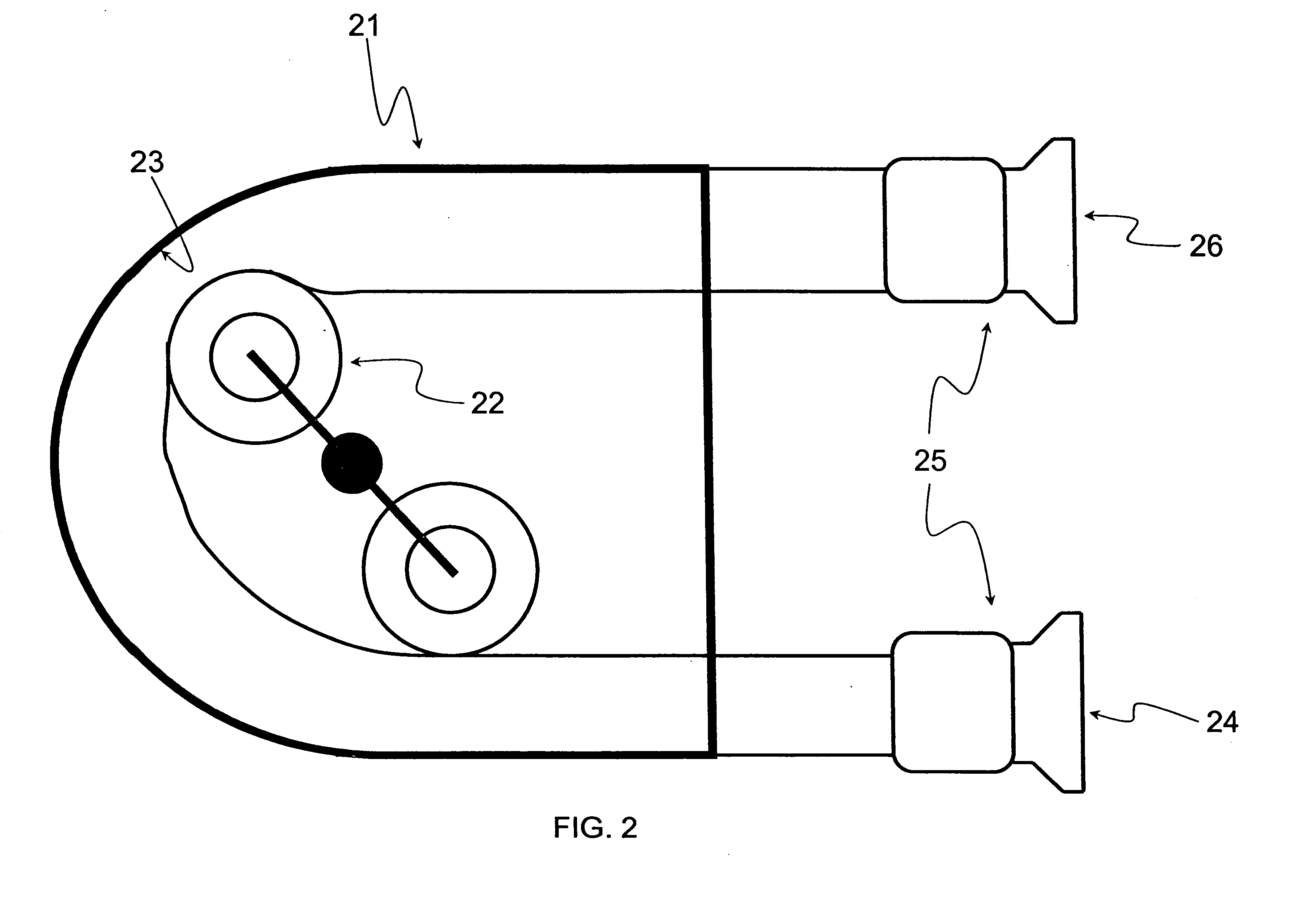
[0001] This application claims benefit of provisional application No. 60 / 590,290 filed Jul. 21, 2004.FIELD OF THE INVENTION [0002] The present invention is directed to a durable fluoroplastic composite elastomer. BACKGROUND OF THE INVENTION [0003] Peristaltic pumps are used in numerous applications that require low shear pumping, portability, ability to run dry, ease of cleaning, accurate dosing, etc. These applications can be found in industries ranging from pharmaceutical manufacturing to food processing to water treatment. [0004] The basic principle of peristaltic pumping involves the rotation of a central rotor containing either rollers or fixed shoes against a resilient elastomeric tube surrounding the rotor that is compliant enough to allow for complete collapse from the rotating rollers, and yet elastic enough to recover to a circular cross-section (referred to as restitution) once the rollers pass, thus enabling the next segment of tubing to fill with the process fluid and m...

Claims


Application Information

Patent Timeline
Patent Type & Authority Applications(United States)
IPC IPC(8): F04B45/06F04B43/12
CPCF04B43/0054F04B43/1253F05C2225/04Y10T428/24942Y10T428/139Y10T428/1379Y10T428/2495Y10T428/13Y10T428/1386Y10T428/24967Y10T428/1393Y10T428/1352Y10T428/3154Y10T428/31544Y10T428/31909Y10T428/31928Y10T428/31931Y10T428/31913Y10T428/31935Y10T428/31917Y10T428/31924Y10T428/31826
Inventor ZUMBRUM, MICHAEL ALLEN
Owner MAZTECH
Learn More