

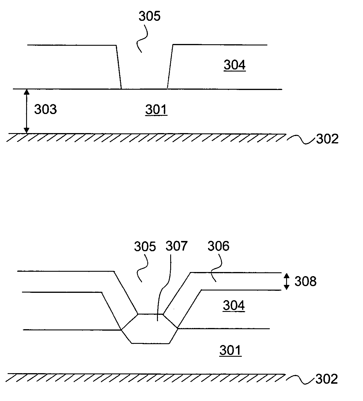
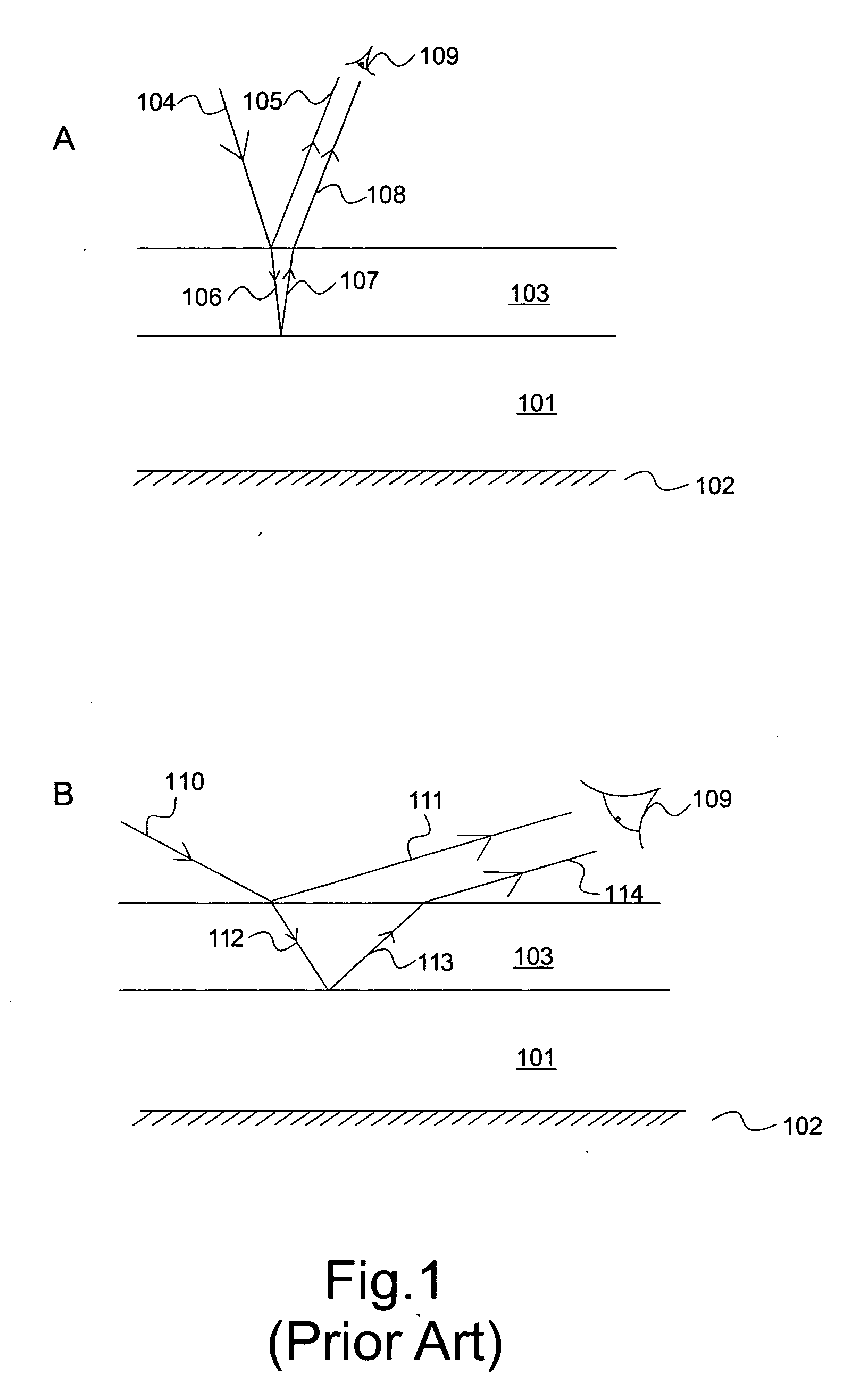
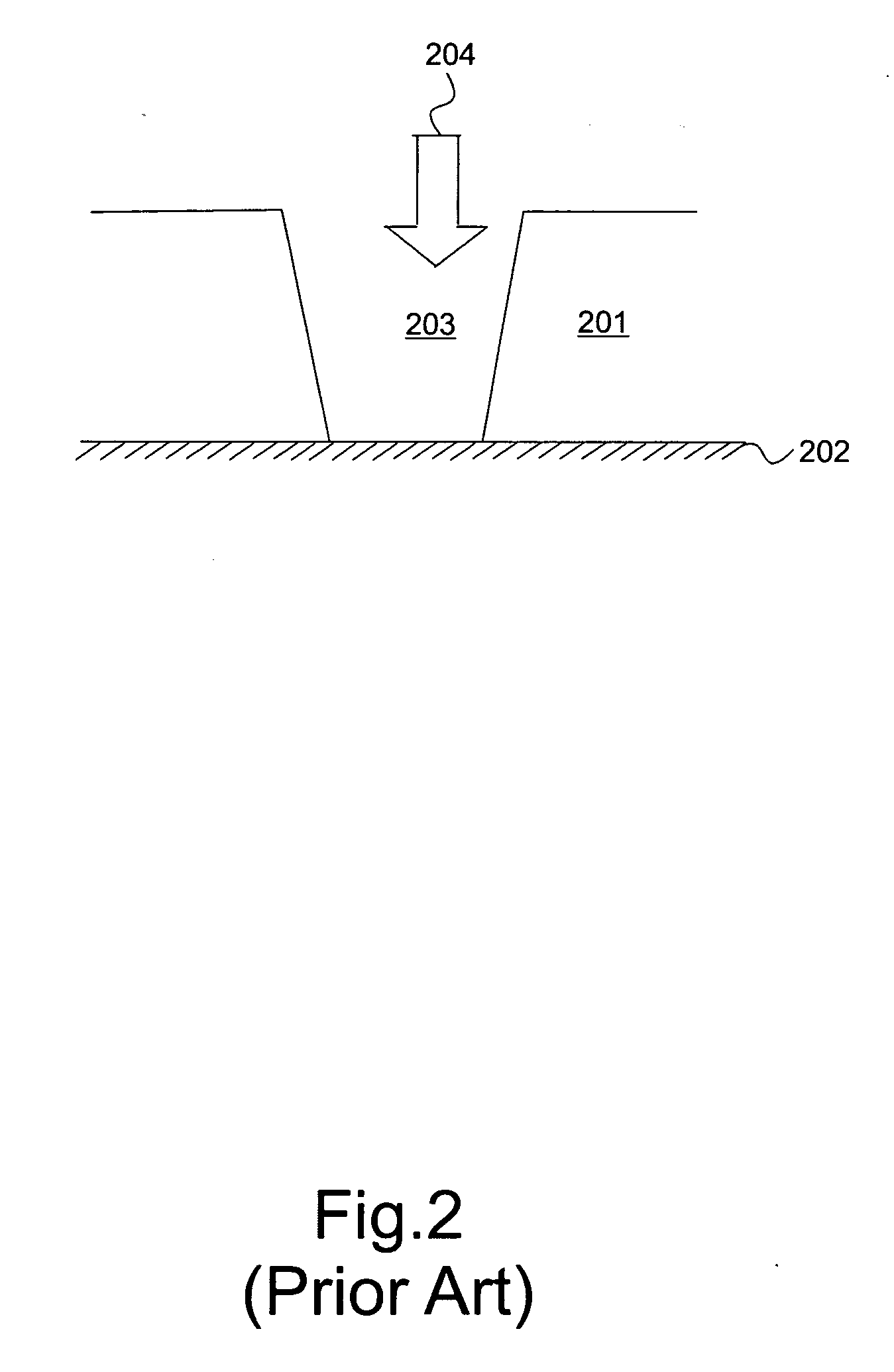
Base for decorative layer
a technology of decorative layer and base layer, applied in the field of decorative layer, can solve the problems of interference with incident light, limited colour range, light travel, etc., and achieve the effect of improving the thickness toleran
- Summary
- Abstract
- Description
- Claims
- Application Information
AI Technical Summary
Benefits of technology
Problems solved by technology
Method used
Image

Examples
example
[0110] To further illustrate the range of colours that can be achieved using anodic oxide layers, FIG. 12 shows the colours produced by different anodic oxide layers comprising different materials at different voltages. The colours are defined by means of the CIE L*a*b* system. These are for layers of aluminium, titanium, niobium, tantalum and a titanium / aluminum alloy. The surface layers have been anodized using electric fields ranging from ten volts to 130 volts.
[0111] Whilst the CIE L*a*b* system accurately describes the colours of the layers, to further illustrate the colours that can be obtained, when a niobium layer is anodized using an electric field ranging from 10 volts to 90 volts, the observed interference colour of the surface ranges from gold to purple to blue to light grey to silver to yellow to pink to purple to turquoise to green.
PUM
| Property | Measurement | Unit |
|---|---|---|
| Grain size | aaaaa | aaaaa |
| Grain size | aaaaa | aaaaa |
| Temperature | aaaaa | aaaaa |
Abstract
Description
Claims
Application Information