Fuel cell with fuel monitoring system and method of use
- Summary
- Abstract
- Description
- Claims
- Application Information
AI Technical Summary
Problems solved by technology
Method used
Image

Examples
Embodiment Construction
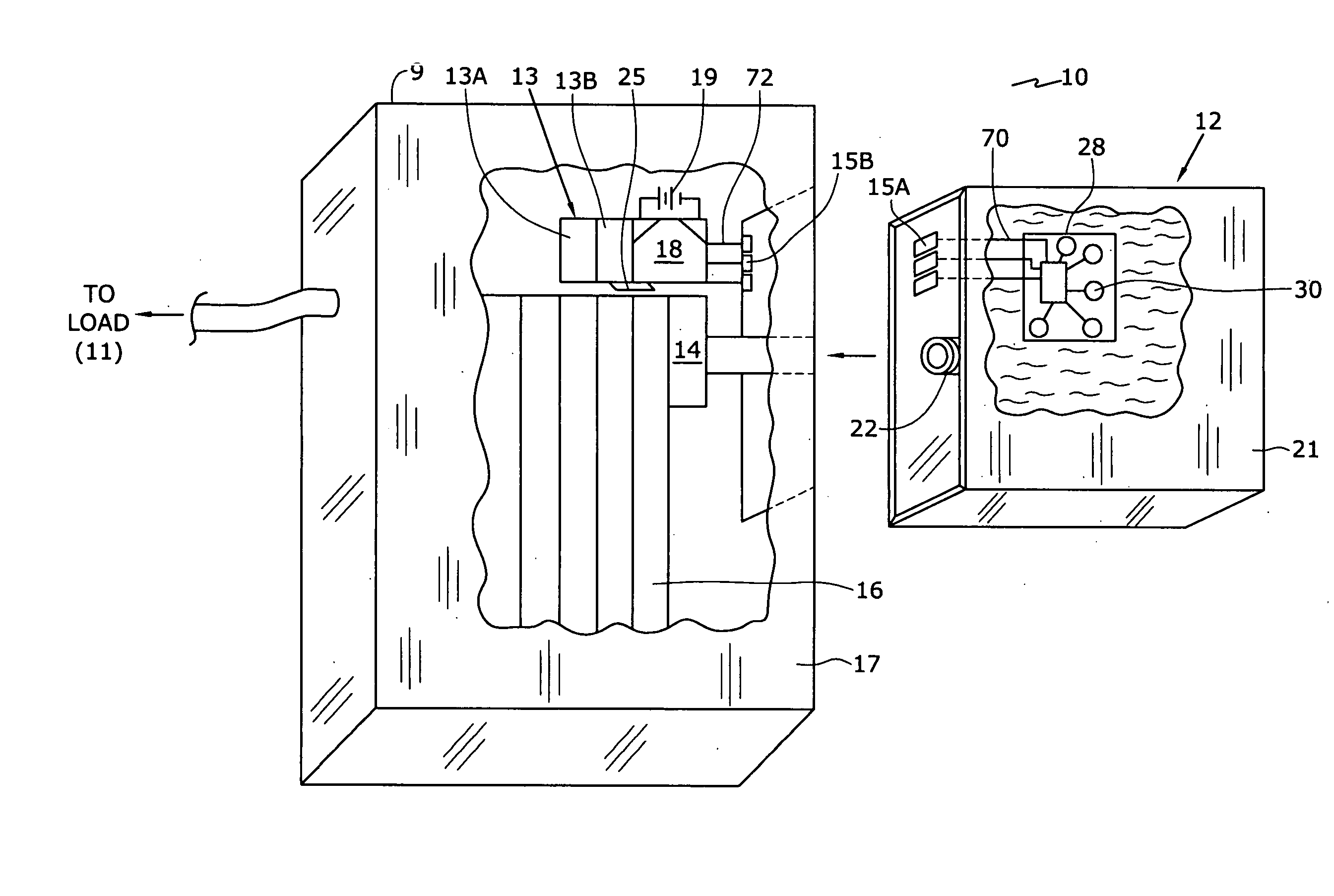
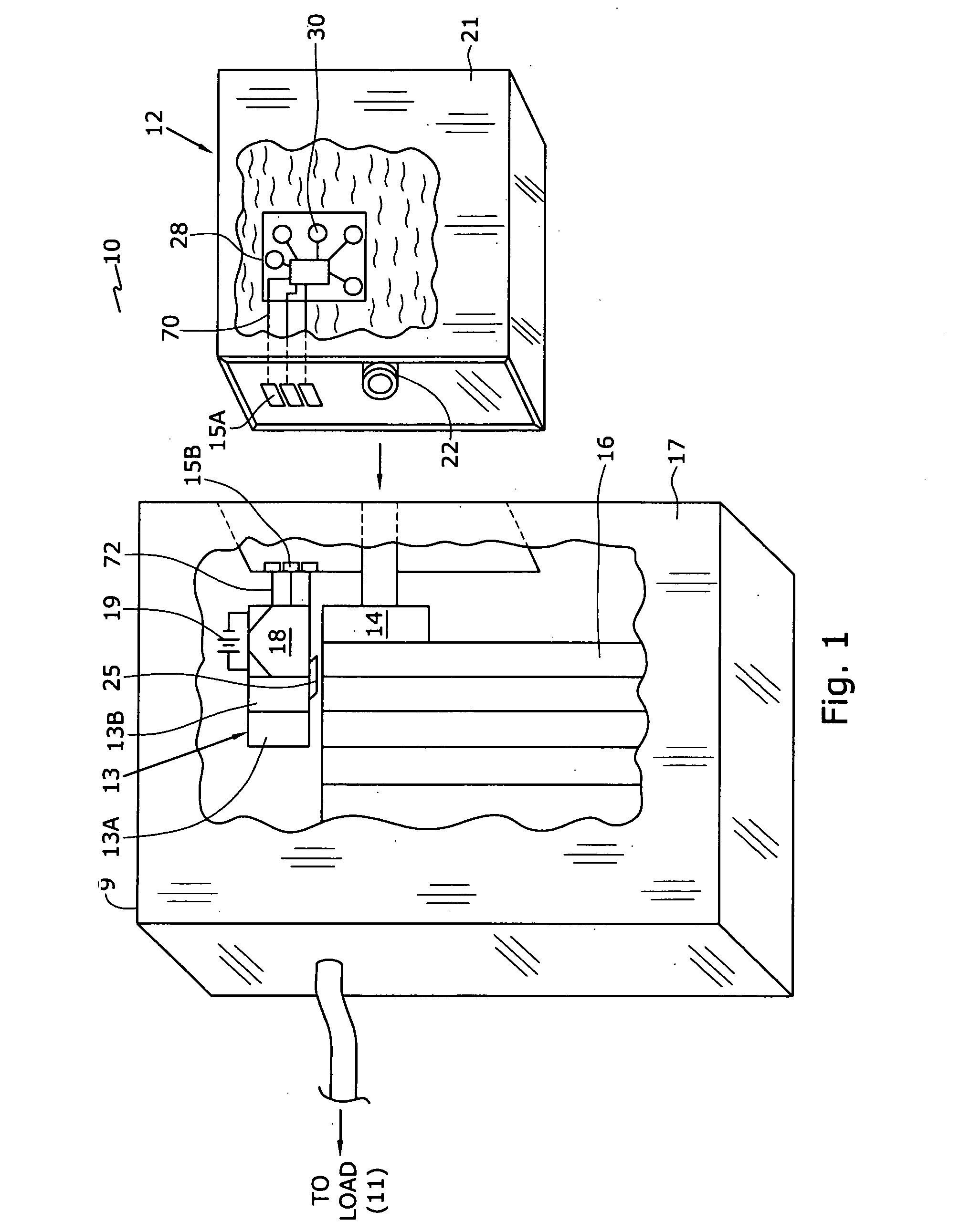
[0043] As illustrated in the accompanying drawings and discussed in detail below, the present invention is directed to a fuel supply, which stores fuel cell fuels such as methanol and water, methanol / water mixture, methanol / water mixtures of varying concentrations or pure methanol. Methanol is usable in many types of fuel cells, e.g., DMFC, enzyme fuel cell and reformat fuel cell, among others. The fuel supply may contain other types of fuel cell fuels, such as ethanol or other alcohols, chemicals that can be reformatted into hydrogen, or other chemicals that may improve the performance or efficiency of fuel cells. Fuels also include potassium hydroxide (KOH) electrolyte, which is usable with metal fuel cells or alkali fuel cells, and can be stored in fuel supplies. For metal fuel cells, fuel is in the form of fluid borne zinc particles immersed in a KOH electrolytic reaction solution, and the anodes within the cell cavities are particulate anodes formed of the zinc particles. KOH e...
PUM
| Property | Measurement | Unit |
|---|---|---|
| Distance | aaaaa | aaaaa |
| Distance | aaaaa | aaaaa |
| Magnetism | aaaaa | aaaaa |
Abstract
Description
Claims
Application Information
PatSnap Eureka turns technology decisions into work you can execute. Powered by our Innovation Knowledge Graph, it runs expert workflows across engineering, life sciences, materials and intellectual property. Get your review-ready output in minutes.


