Control of reactor environmental conditions

Inactive Publication Date: 2006-01-26
BIOPROCESSORS CORP
View PDF98 Cites 59 Cited by
  • Summary
  • Abstract
  • Description
  • Claims
  • Application Information

AI Technical Summary

Benefits of technology

[0019] Other advantages and novel features of the present invention will become apparent from the following detailed description of various non-limiting embodiments of the invention when considered in conjunction with the accompanying figures. In cases where the present specification and a document

Problems solved by technology

As is appreciated in the art, providing and maintaining suitable culture conditions for cell viability and growth in such small-scale systems can be extremely difficult.
Typical materials utilized for fabrication of such small-scale bioreactors often are not ideally suited for establishing and ma

Method used


Image

  • Control of reactor environmental conditions
  • Control of reactor environmental conditions
  • Control of reactor environmental conditions

Examples


example 1

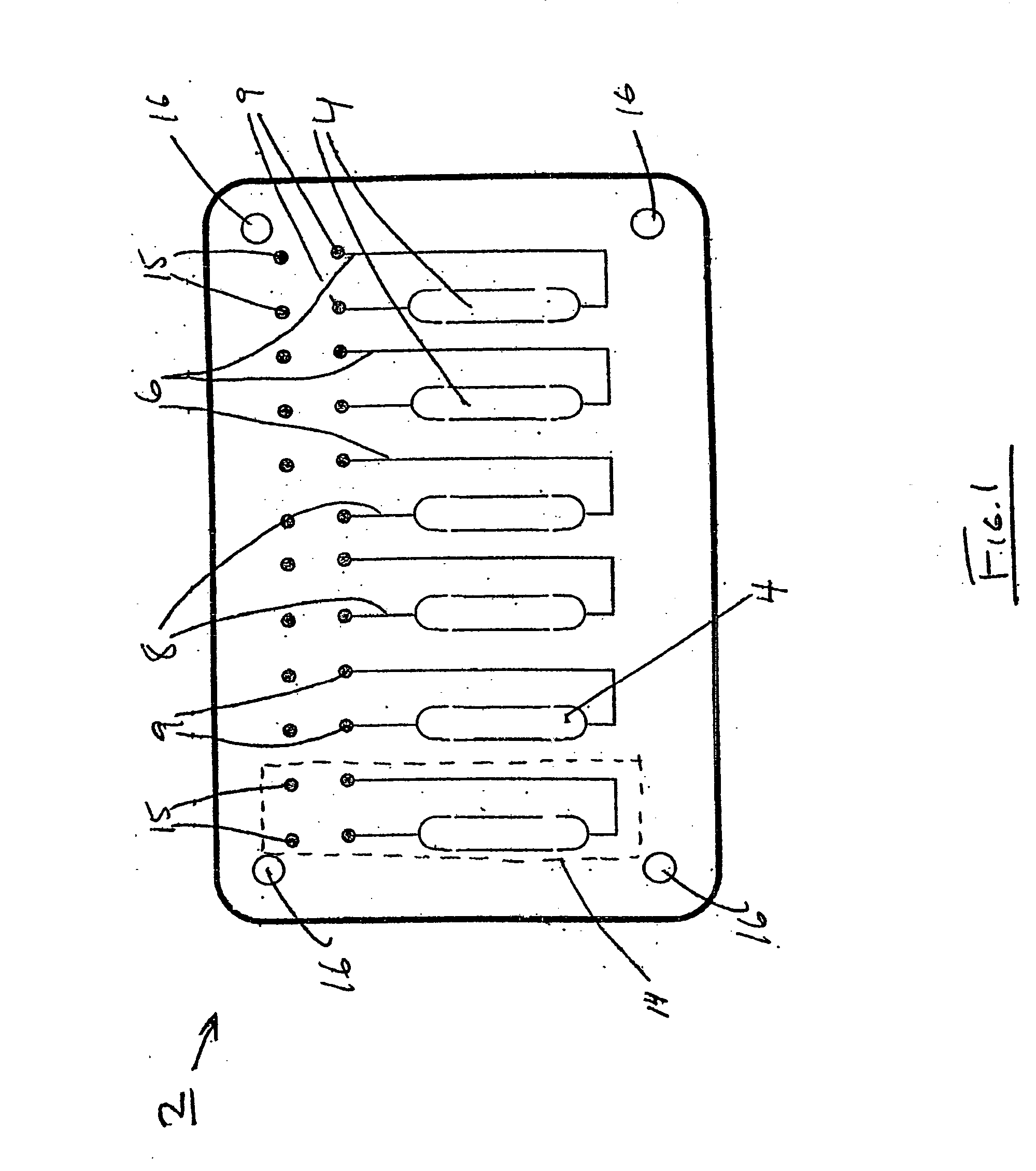
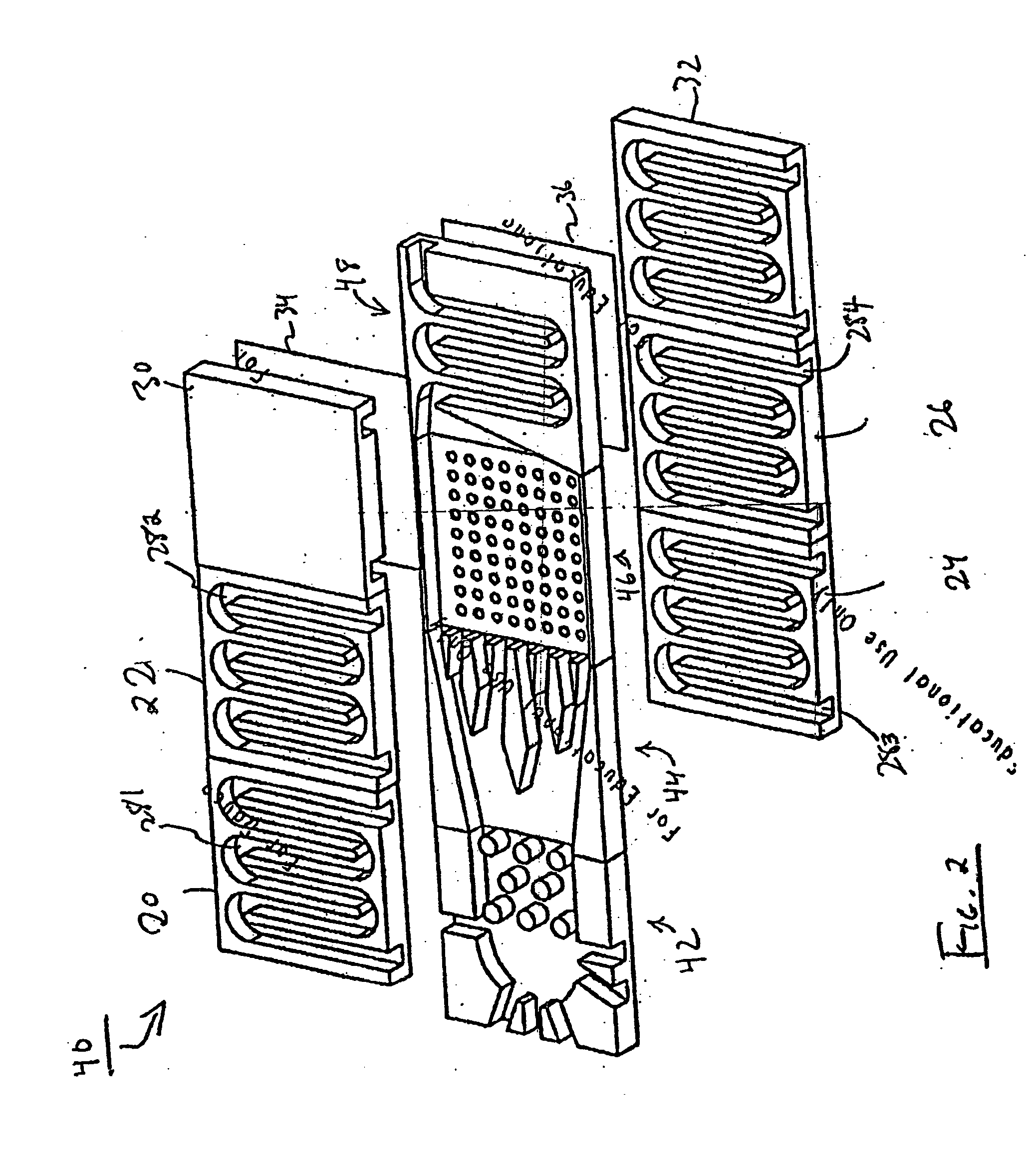
[0189] In this example, an exemplary chip, as illustrated generally in FIG. 4A, is prepared. A first chip layer having associated fluidic channels, ports, compartments, other reaction sites, etc. therein is injection molded or machined from a stock sheet of acrylic or polycarbonate. This first layer is attached to a machined or injection molded flat bottom plate (also acrylic or polycarbonate) by means of a pressure-sensitive silicone adhesive (Dielectric Polymers). A humidity control membrane comprising one or more of the materials described above for forming humidity control layers / membranes is also attached to the top side of the first layer by means of the pressure-sensitive silicone adhesive.

[0190] A second chip layer (including a top) having associated fluidic channels, ports, compartments, other reaction sites, etc. therein is cast in a mold using PDMS. This second layer is fashioned to be alignable with the first chip layer. The second layer is aligned with the compartments...

example 2

[0191] This example illustrates various chips formed from multiple layers of dissimilar materials. A variety of adhesives can be used to fix the interface layers to the rigid cell culture or sealing layers depending on the materials involved. One adhesive that can be used for bonding PDMS to polycarbonate is a two-part urethane epoxy mixed with un-cured PDMS. The adhesive process used to bond rigid polycarbonate layers to each other can be either sonic welding or a heated press. The reaction site is designed, in this example, to be about 200 microns thick and had a volume of roughly 20 microliters.

[0192] A chip 280 having reaction site 240 is fabricated. As shown in FIG. 8A, a polycarbonate layer 244 is attached to a humidity control material of the invention 242. A gap within the material 242 defines reaction site 240 when the chip was assembled, as shown in FIG. 8A. Material 242 is attached to polycarbonate layer 244.

[0193] A similar chip is illustrated in FIG. 8B. In this figur...

example 3

[0194] This example illustrates various chips formed from multiple layers of dissimilar materials. A variety of adhesives can be used to fix the interface layers to the rigid cell culture or sealing layers depending on the materials involved. One example adhesive used for bonding PDMS to polycarbonate is a two-part urethane epoxy mixed with un-cured PDMS. The adhesive process used to bond rigid polycarbonate layers to each other can be, for example, sonic welding or a heated press. The reaction site is designed, in this example, to be about 200 microns thick and had a volume of roughly 20 microliters.

[0195] The fabrication of the chips illustrated in FIGS. 9A and 9B is similar to those described in Example 2, including the adhesion methods. In FIG. 9A, the reservoir layer 248 is fashioned from polycarbonate and was positioned between a humidity control material of the invention 246 and polycarbonate layer 244. Reservoir layer 248 has a gap (i.e., a hole or a partially hollowed out ...


PUM


Abstract

The present disclosure generally relates to chemical, biological, and/or biochemical reactor chips and/or reaction systems such as microreactor systems, as well as methods for constructing and using such systems. In some cases, humidity control materials are utilized to provide beneficially high rates of gas exchange. The humidity control materials may be used, in certain instances, to provide at least adequate, and in certain embodiments superior, gas exchange for systems having small volumes. In some cases, the currently disclosed materials include certain polymers, e.g., poly(acetylene)s such as poly(alkylacetylene)s. The polymers may be at least partially halogenated (for example, fluorinated) in some instances. In certain embodiments, a chip and/or a reaction system may be constructed so as to promote cell growth within it. In some embodiments, the chips may include one or more reaction sites. The reaction sites can be very small, for example, with a volume of less than about 1 ml. In certain embodiments, a reaction system is able to detect, measure and/or control an environmental factor such as the temperature, pressure, CO2 concentration, O2 concentration, relative humidity, pH, etc., associated with one or more reaction sites, by using one or more sensors, actuators, processors, and/or control systems. In certain embodiments, the present disclosure discloses materials and systems having humidity and/or gas control, for example, for use with a reaction system. Such materials may have high oxygen permeability and/or low water vapor permeability. In certain embodiments, the disclosed devices can employ light-interacting components suitable for use in reaction systems. These components may include waveguides, optical fibers, light sources, photodetectors, optical elements, and the like.

Description

RELATED APPLICATIONS [0001] This application claims the benefit of U.S. Provisional Patent Application Ser. No. 60 / 577,985, filed Jun. 7, 2004, entitled “Control of Reactor Environmental Conditions,” by Rodgers, et al., incorporated herein by reference.FIELD OF THE INVENTION [0002] The present invention generally relates to chemical, biological, and / or biochemical reactor chips and / or reaction systems such as microreactor systems, and, in particular, to chemical, biological, and / or biochemical reactor chips having humidity control materials. BACKGROUND [0003] A wide variety of reaction systems are known for the production of products of chemical and / or biochemical reactions. Chemical plants involving catalysis, biochemical fermenters, pharmaceutical production plants, and a host of other systems are well-known. Biochemical processing may involve the use of a live microorganism (e.g., cells) to produce a substance of interest. [0004] Cells are cultured for a variety of reasons. Incre...

Claims


Application Information

Patent Timeline
IPC IPC(8): C12P1/00B01D61/00B01J19/00B01L3/00C12M3/06C40B60/14
CPCB01D61/002C40B60/14B01J2219/00317B01J2219/00743B01J2219/00783B01J2219/00822B01J2219/00831B01J2219/00833B01J2219/0086B01J2219/00862B01J2219/00873B01J2219/00889B01J2219/00907B01J2219/00961B01J2219/0097B01L3/5025B01L3/502707B01L2200/12B01L2200/143B01L2300/0816B01L2300/0887B01L2300/10B01L2300/12B01L2300/163B01L2300/1822B01L2400/046C12P1/00B01J19/0093B01D61/005
Inventor RODGERS, SETH T.RUSSO, A. PETERLEBLANC, SEAN J.LEROUX, DENIS F.
Owner BIOPROCESSORS CORP
Why Eureka
Try Eureka