Immobilization of cells in a matrix formed by biocompatible charged polymers under laminar flow conditions

a charge polymer and matrix technology, applied in the field of immobilization of cells in a matrix formed by biocompatible charged polymers under laminar flow conditions, can solve the problems of inability to manipulate or control the interaction of different cells, cell growth and prolongation of cell survival, and limited co-culture, etc., to achieve excellent stability of the polymer strip, improve the stability of the polymer, and improve the effect of cell survival

Inactive Publication Date: 2006-01-26
AGENCY FOR SCI TECH & RES
View PDF3 Cites 31 Cited by
  • Summary
  • Abstract
  • Description
  • Claims
  • Application Information

AI Technical Summary

Benefits of technology

[0034] One advantage of the present invention is the formation of a physically stable three-dimensional polymer matrix in form of a ‘polymer strip’. Due to the excellent stability of this polymer strip, it can be peeled out of the flow device using for example the method as described by W. Tan and T. A. Desai (Biomaterials, 2004, Vol. 25, P. 1355-1364). After peeling the polymer strip out of the canal, the polymer strip can be fixed on biochips for imaging and biological studies or be used in biosensors and bioreactors, to name only a few options. To achieve an even more stable polymer strip a configuration of laminar polymer streams as illustrated in FIG. 3D and described in more detail further below can be used in which the laminar stream of a cell containing second charged polymer is sandwiched between two laminar streams of a first charged polymer.
[0035] Examples of flow devices that can be used for the method of the present invention are shown in FIGS. 1 and 2. A suitable flow device typically comprises two or more inlet openings 3 that are fluidly connected to the reaction canal 2, for example, via canals 5 to allow laminar polymer streams to flow into the reaction canal 2. In addition such a flow device usually further comprises one or more outlet opening(s) 4 that are fluidly connected via perpendicularly or transversely orientated canals 5 to the reaction canal 2. The arrangement and number of canals 5 and openings 3, 4 that lead to or away from the reaction canal 2 depends on the desired configuration of the laminar polymer streams that polymerize to form the three-dimensional polymer matrix within the reaction canal 2.
[0036] Examples for different configurations of laminar polymer flows are shown in FIG. 3. If one or more cell species are to be embedded in the same second charged polymer the laminar polymer streams might be arranged as depicted in FIGS. 3A and 3B. For this configuration of laminar polymer streams a flow device with inlet and outlet openings positioned as shown in FIG. 1A might be used. Described in more detail, in FIG. 3A a laminar polymer stream of a first charged polymer (A) flows side by side to a laminar polymer stream of a second charged polymer (B), whereas in FIG. 3B the two polymer streams (A) and (B) are stacked on top of each other. Once the reaction canal is filled to the desired length of the later formed polymer strip, the first and second charged polymer polymerize to form the three dimensional polymer matrix embedding the cells.
[0037] An arrangement of canals as shown in FIG. 1A is advantageous, if further experiments and tests are to be carried out directly within the canal of the flow device. The use of a flow device as depicted in FIGS. 2A and 2D allows an arrangement of different laminar polymer streams as depicted in FIG. 3D. In this configuration the laminar polymer stream of a second charged polymer (B) containing the cells is sandwiched between two laminar polymer streams of first charged polymers A and Z, wherein the laminar polymer streams of first charged polymers A and Z can contain the same or different first charged polymers depending on the desired form of the polymer matrix formed. This sandwich arrangement enables the production of an even more stabilized polymer strip compared to

Problems solved by technology

Some cells can only grow and prolong their cell survival in co-cultures of different cell types.
However, co-cultures have been limited by the inability to manipulate or control the interaction of the different cells in the culture due to the lack of a suitable matrix for these cells.
However, this approach is limited to the patterning of

Method used


Image

  • Immobilization of cells in a matrix formed by biocompatible charged polymers under laminar flow conditions
  • Immobilization of cells in a matrix formed by biocompatible charged polymers under laminar flow conditions
  • Immobilization of cells in a matrix formed by biocompatible charged polymers under laminar flow conditions

Examples


example 1

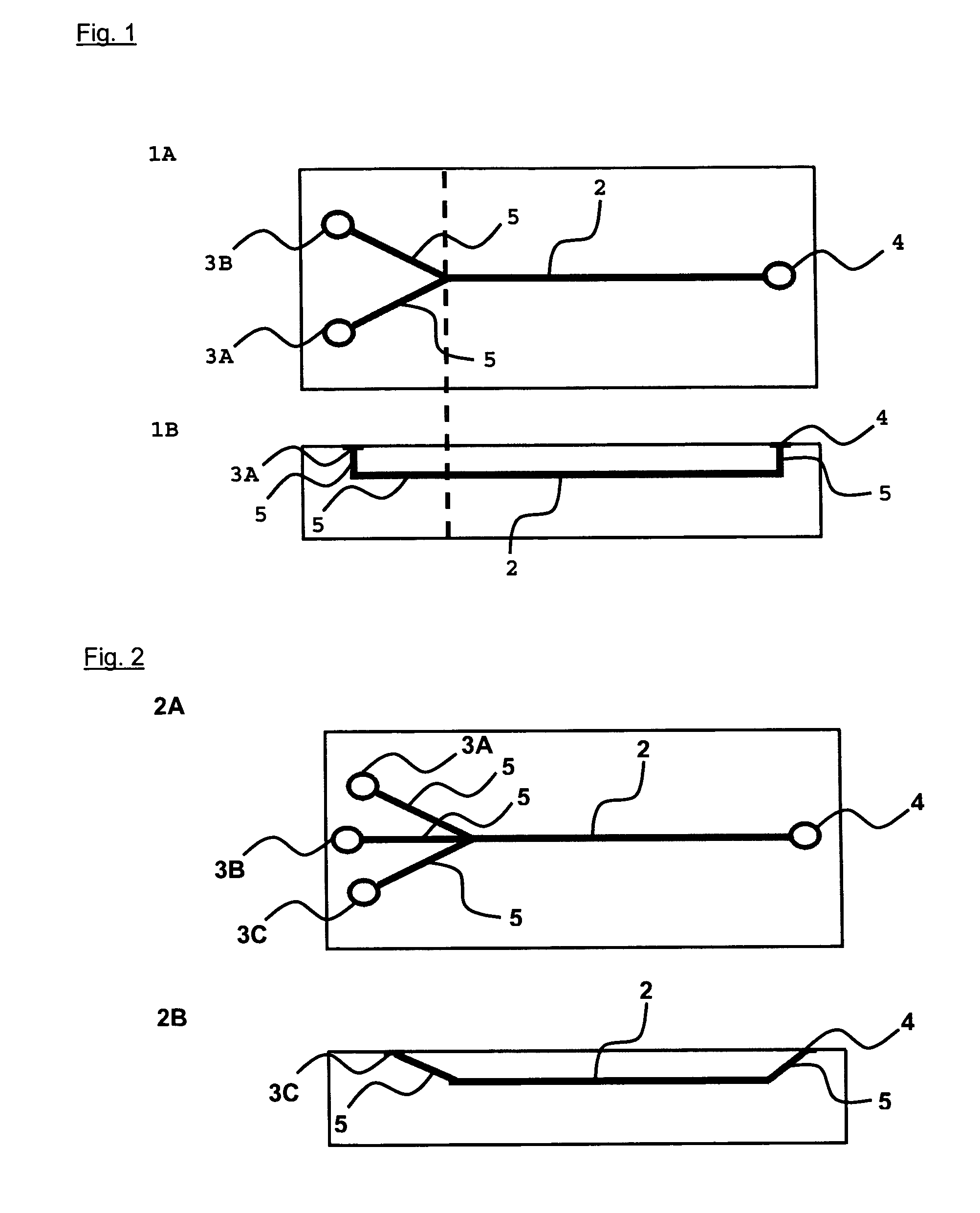
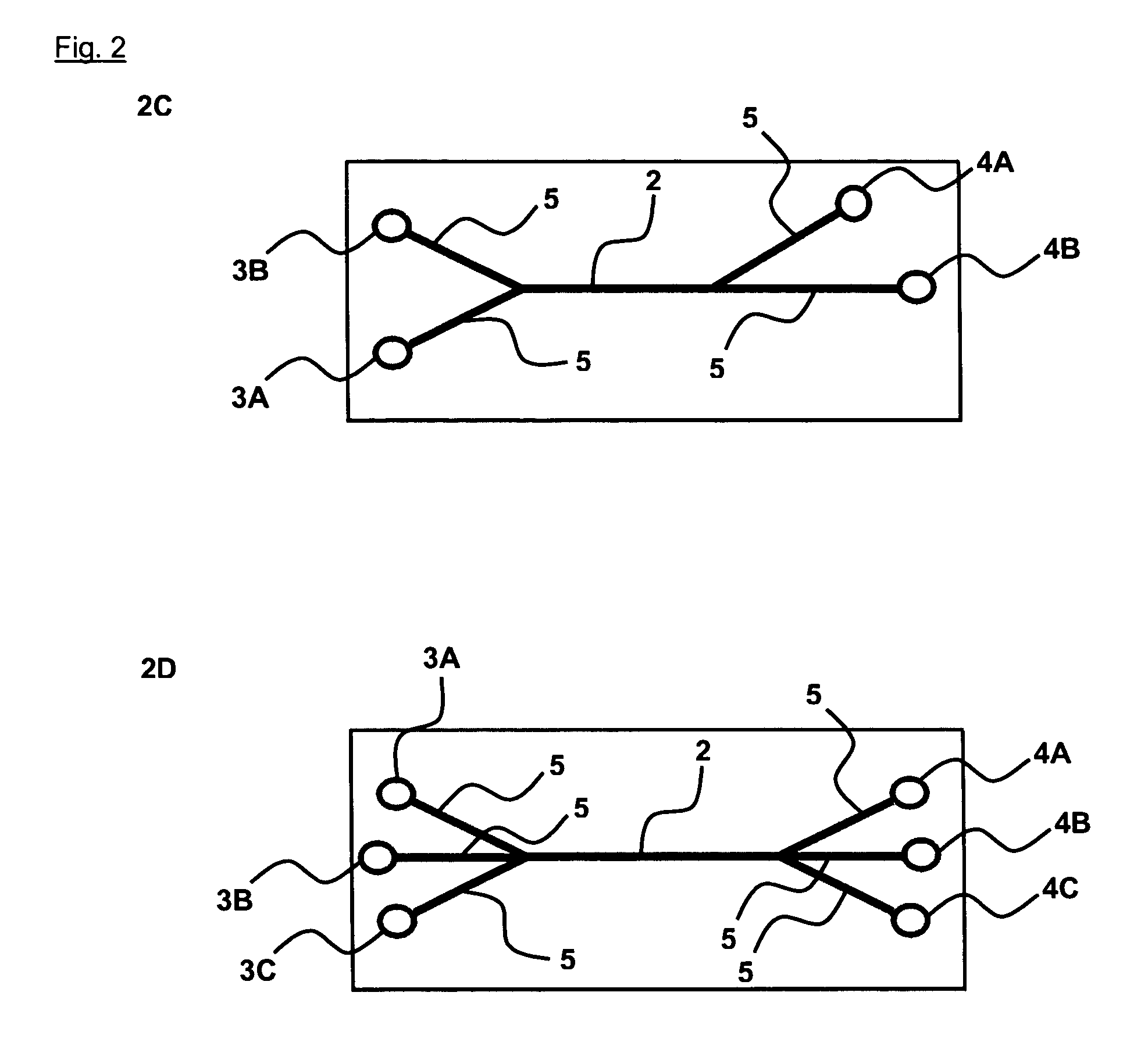
[0064] Example 1 illustrates the in situ formation of a polymer matrix by laminar reaction of methylated (positively charged) collagen as second charged polymer and (negatively charged) terpolymer of hydroxylethyl methacrylate-methyl methacrylate-methyl acrylic acid (HEMA-MMA-MM) as first charged polymer under laminar flow conditions.

[0065] In this example two different combinations of this polymers are used that are composed of different concentrations of collagen and terpolymer of different molecular weight. The formation of a polymer matrix is based on the polyelectrolyte complex coacervation between cationic methylated collagen and anionic terpolymer of HEMA-MMA-MM. This polymer matrix has been shown to provide favorable three dimensional microenvironment for cell support and proliferation (Chia et al., Tissue Engineering 2000, Vol. 6(5), P. 481-495). Two different polymer combinations are used to illustrate the control of the structure of the polymer matrix formed using differ...

example 2

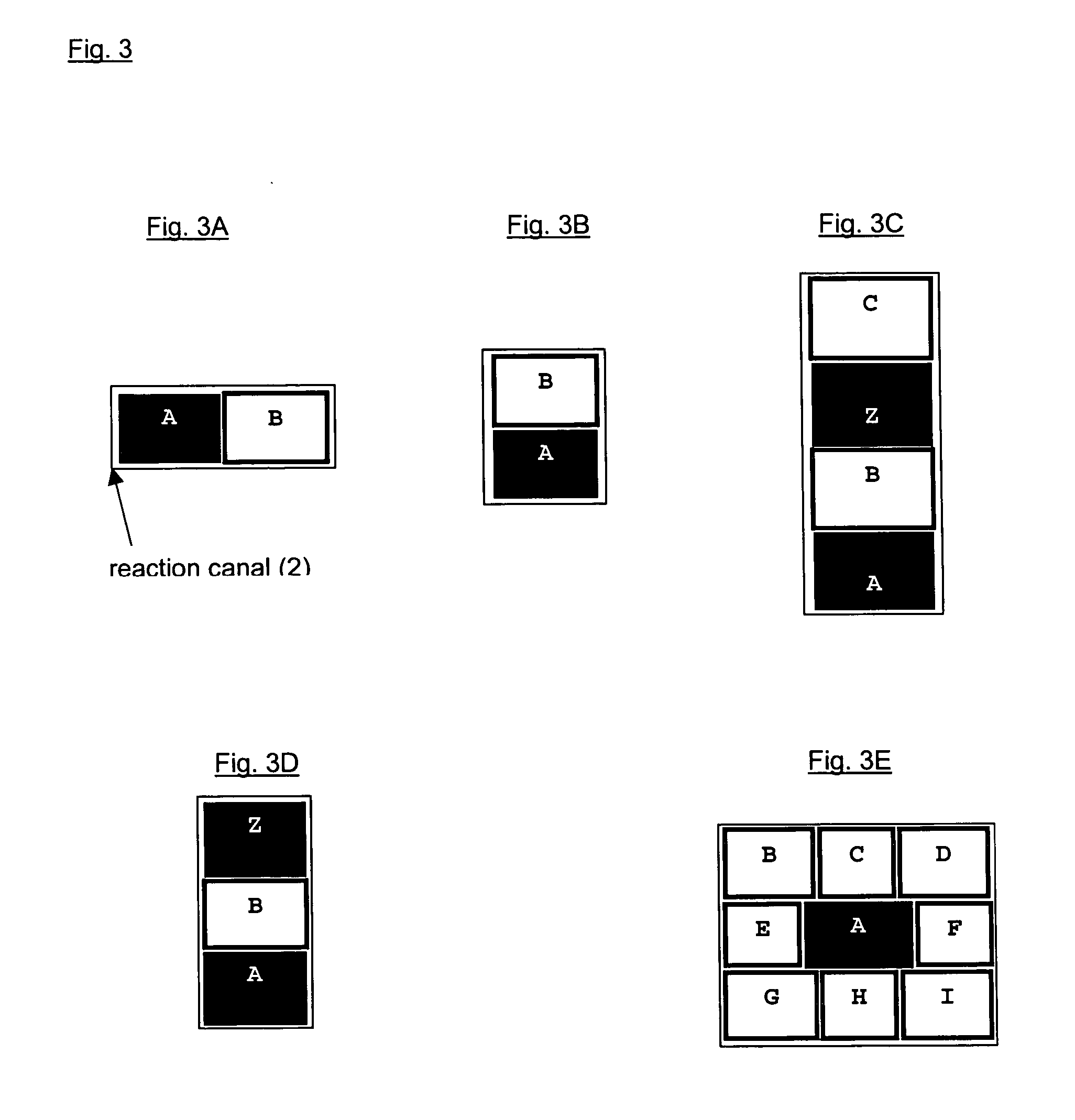
[0074] This example shows the ability of the three dimensional polymer matrix to be perfused with analyte containing liquid media. For this purpose, detoxification functions of hepatocytes embedded in a polymer matrix formed by laminar side-by-side flows (as schematically shown in FIG. 3A) of methylated collagen and terpolymer of hydroxylethyl methacrylate-methyl methacrylate-methyl acrylic acid (HEMA-MMA-MAA) were studied.

[0075] For this experiment, freshly isolated primary rat hepatocytes were suspended in methylated collagen, and the cell-containing methylated laminar collagen stream was complex coacervated with an adjacent laminar stream of terpolymer. The hepatocytes embedded in the formed polymer matrix were cultured for 24h and the hepatocytes detoxification functions assessed by their 7-ethoxyresorufin O-dealkylation (EROD) activities. The methylated collagen and the terpolymer HEMA-MMA-MAA used in this experiment were obtained as described in Example 1. Also the PDMS micro...

example 3

[0079] This example illustrates the use of the polyelectrolyte complex coacervation reaction between methylated collagen as second charged polymer and terpolymer of HEMA-MMA-MM as first charged polymer to manipulate the formation of collagen matrices which have an important bearing on cellular behavior. Collagen of different methylation degrees is used to complex coacervate with terpolymer to alter polymer matrix morphology to engineer microenvironments for optimal cell support. Two liver-derived model cell types, primary hepatocytes and HepG2 cell line are chosen to study the effect of polymer matrix morphology on cellular functions. Primary hepatocytes represent primary cells that are highly sensitive, terminally differentiated and require specific chemical and topological extra-cellular matrix (ECM) cues for the maintenance of differentiated functions in vitro, while HepG2 is a hepatic cell line that represents transformed cell lines which can proliferate relatively easily in cul...


PUM


Abstract

This invention relates to a method for immobilizing cells under laminar flow conditions in a matrix formed by biocompatible charged polymers, to a flow device for the use with the method of the present invention, and to uses of the polymer matrices containing the cells immobilized using the method of the present invention.

Description

[0001] The invention relates to a method for immobilizing cells under laminar flow conditions in a polymer matrix formed by biocompatible charged polymers, to a flow device for the use with the method of the present invention, and to uses of the polymer matrices containing the cells immobilized using the method of the present invention. BACKGROUND OF THE INVENTION [0002] Tissues in vivo have highly organized complex three-dimensional structures that comprise of heterogeneous cell populations and extra-cellular matrix (ECM). In mammals, the ECM can surround cells as fibrils, tubes and channels that contact the cells on all sides, or as a sheet called the basement membrane that cells ‘sit on’. The ECM is normally composed of proteins and polysaccharides to provide mechanical support and a biochemical barrier. A modified form of ECM for example appears in form of bone. Research has shown that the functioning of cells is very much influenced by cell extracellular matrix. Some cells can ...

Claims


Application Information

Patent Timeline
IPC IPC(8): C12N11/02C12N5/07C12N5/071C12N5/074
CPCC12N5/0068C12N2533/54C12N2533/30C12N11/04
Inventor NG, SAN SAN SUSANNEYU, HANRY
Owner AGENCY FOR SCI TECH & RES
Why Eureka
Try Eureka