Vehicle and method for operating a vehicle to reduce exhaust emissions

a technology of exhaust emissions and vehicles, applied in hybrid vehicles, exhaust treatment electric control, electrical control, etc., can solve the problems of relying on a separate, and reducing the efficiency of the engine, so as to reduce the emission, reduce the emission, and reduce the effect of exhaust emissions

Active Publication Date: 2006-02-02
FORD GLOBAL TECH LLC
View PDF19 Cites 3 Cited by
  • Summary
  • Abstract
  • Description
  • Claims
  • Application Information

AI Technical Summary

Benefits of technology

[0009] One advantage of the present invention is that it provides a vehicle and a method for operating a vehicle that reduces the release of exhaust emissions into the atmosphere following engine start-up.
[0010] Another advantage of the invention is that it reduces emissions while still providing driver demanded power.
[0011] The invention also provides a method for operating a vehicle to reduce exhaust emissions. The vehicle includes an engine, an electric machine, an energy storage device capable of providing energy to operate the electric machine, and a catalyst for facilitating a reaction in exhaust gas from the engine. The method includes setting at least one engine parameter to effect an increase in a rate of temperature increase of the catalyst when the engine is operating. This decreases the time required for the catalyst to reach a temperature whereat emissions are reduced. The engine is operated such that the engine output power is generally constant when an output power of the energy storage device is within a first predetermined range. The at least one engine parameter is adjusted, thereby changing the engine output power, when the output power of the energy storage device is outside the first predetermined range. The at least one engine parameter is adjusted to facilitate a change in the output power of the energy storage device from outside the first predetermined range into the first predetermined range.
[0012] The invention further provides a method for operating a vehicle to reduce exhaust emissions. The vehicle includes an engine, an electric machine, an energy storage device capable of providing energy to operate the electric machine, and a catalyst for facilitating a reaction in exhaust gas from the engine. The method includes determining a desired output power for the vehicle. The vehicle is operated in a first mode when at least one predetermined condition is met. The first mode includes providing at least some of the desired vehicle output power with the electric machine when the desired vehicle output power is nonzero. At least one engine parameter is set to effect an increase in a rate of temperature increase of the catalyst when the engine is operating. The engine is operated such that engine output power is generally constant when an output power of the energy storage device is within a first predetermined range. The first mode also includes adjusting the at least one engine parameter, thereby changing the engine output power, when the output power of the energy storage device is outside the first predetermined range. The at least one engine parameter is adjusted to facilitate a change in the output power of the energy storage device from outside the first predetermined range into the first predetermined range. The method also includes operating the vehicle in a second mode when the at least one predetermined condition is not met. The second mode includes operating the engine at least partly based on the desired vehicle output power and a state of the energy storage device.
[0013] The invention also provides a vehicle that includes an engine, an electric machine operable to drive the vehicle, and an energy storage device capable of providing energy to operate the electric machine. The vehicle also includes a catalyst capable of facilitating a reaction in exhaust gas from the engine, and at least one controller. The at least one controller is configured to set at least one engine parameter to effect an increase in a rate of temperature increase of the catalyst when the engine is operating. This decreases the time required for the catalyst to reach a temperature whereat emissions are reduced. The at least one controller is further configured to control the engine to provide a generally constant output power when an output power of the energy storage device is within a first predetermined range. The controller is further configured to adjust the at least one engine parameter, thereby changing the engine output power, when the output power of the energy storage device is outside the first predetermined range. The at least one engine parameter is adjusted to facilitate a change in the output power of the energy storage device from outside the first predetermined range into the first predetermined range.

Problems solved by technology

One limitation of the use of catalysts is that they tend to be ineffective below a certain activation temperature.
One limitation of the apparatus described in Hirose, is that it relies on a separate device—i.e., the adsorbent—to augment the catalyst as part of an emission control system.
This causes the catalyst to be heated more quickly, but results in a loss of engine power.
Thus, if a driver demands an increases in engine power, the spark retard must be reduced, which causes the catalyst to be heated more slowly, and results in more exhaust emissions being introduced into the atmosphere.
Thus, there is the potential for a great deal of exhaust emissions to be released into the atmosphere during the many times an engine in an HEV is started and operated prior to the catalyst reaching its activation temperature.

Method used


Image

  • Vehicle and method for operating a vehicle to reduce exhaust emissions
  • Vehicle and method for operating a vehicle to reduce exhaust emissions
  • Vehicle and method for operating a vehicle to reduce exhaust emissions

Examples


Embodiment Construction

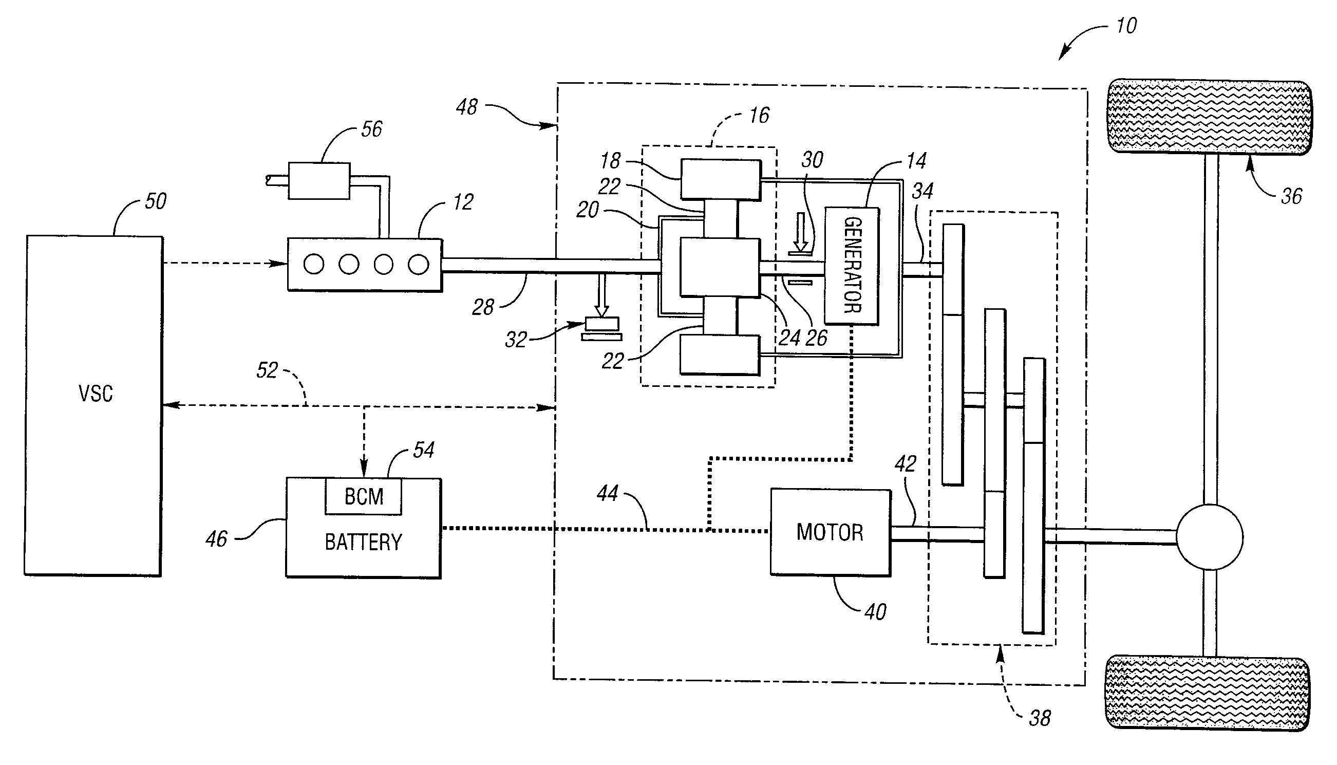
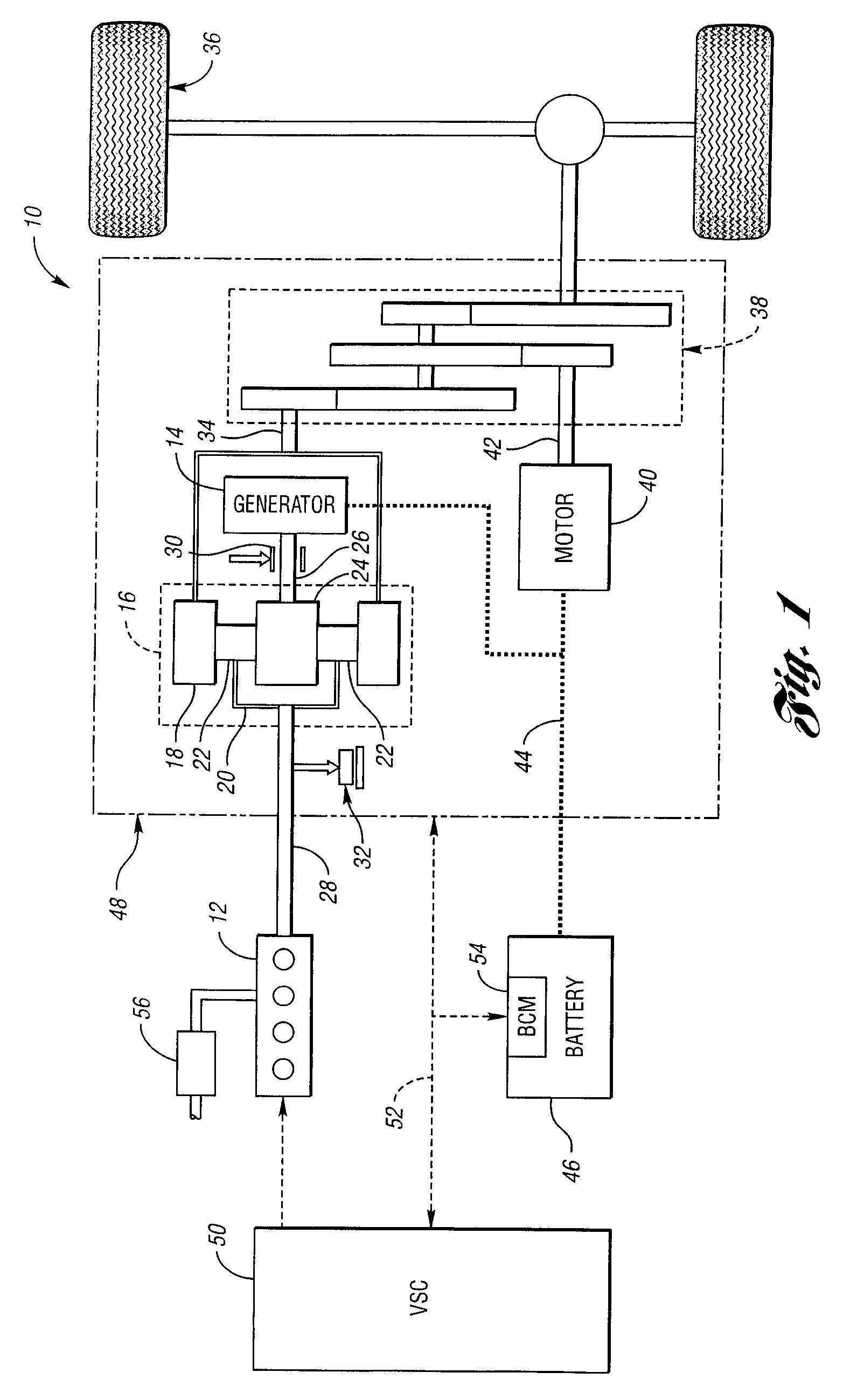
[0018]FIG. 1 shows a schematic representation of a vehicle 10 in accordance with the present invention. The vehicle 10 includes an engine 12 and an electric machine, or generator 14. The engine 12 and the generator 14 are connected through a power transfer unit, which in this embodiment is a planetary gear set 16. Of course, other types of power transfer units, including other gear sets and transmissions may be used to connect the engine 12 to the generator 14. The planetary gear set includes a ring gear 18, a carrier 20, planet gears 22, and a sun gear 24.

[0019] The generator 14 can also be used as a motor, outputting torque to a shaft 26 connected to the sun gear 24. Similarly, the engine 12 outputs torque to a shaft 28 connected to the carrier 20. A brake 30 is provided for stopping rotation of the shaft 26, thereby locking the sun gear 24 in place. Because this configuration allows torque to be transferred from the generator 14 to the engine 12, a one-way clutch 32 is provided ...


PUM


Abstract

A method for operating a vehicle to reduce exhaust emissions is provided. The vehicle includes an engine, a motor, a battery for operating the motor, and a catalyst for reducing exhaust gas emissions. The vehicle is operated in a first mode when at least one predetermined condition is met. The first mode includes providing at least some of the desired vehicle output power with the motor. The engine is operated to quickly increase the temperature of the catalyst when the output power from the battery is within a first predetermined range. When the output power of the battery is outside the first predetermined range, the operation of the engine is adjusted to drive battery operation into the first predetermined range. When the at least one predetermined condition is not met, the vehicle is operated in a second mode based at least partly on driver demand and battery requirements.

Description

BACKGROUND OF INVENTION [0001] 1. Field of the Invention [0002] The present invention relates to a vehicle and a method for operating a vehicle to reduce exhaust emissions. [0003] 2. Background Art [0004] Vehicles have long employed the use of catalysts to reduce engine exhaust emissions. Generally, a catalyst facilitates a reaction between oxygen and unburned hydrocarbons, carbon monoxide, and various nitrogen / oxygen compounds, thereby producing carbon dioxide, nitrogen and water. One limitation of the use of catalysts is that they tend to be ineffective below a certain activation temperature. Thus, below the activation temperature, unburned hydrocarbons, carbon monoxide and nitrogen / oxygen compounds can be exhausted from the vehicle and introduced into the atmosphere. [0005] In order to address this problem, a number of systems have been developed to reduce vehicle emissions prior to a catalyst reaching its activation temperature. One such system is described in U.S. Pat. No. 6,32...

Claims


Application Information

Patent Timeline
Patent Type & Authority Applications(United States)
IPC IPC(8): F01N3/00B60K6/445B60W10/06F02D41/02
CPCB60K6/445B60L2240/445B60W10/06B60W2510/068B60W2510/244Y02T10/6239F02D41/0245F02D41/025F02D2041/1431Y02T10/26F02D41/024Y02T10/12Y02T10/62B60K6/20F01N9/00F02D43/00
Inventor MCGEE, RYANNIESSEN, PAULSYED, FAZALKAPOLNEK, CHRISBUTCHER, JONATHANGARTNER, PAUL
Owner FORD GLOBAL TECH LLC
Why Eureka
Try Eureka