Corrosion resistant fluid conducting parts, methods of making corrosion resistant fluid conducting parts and equipment and parts replacement methods utilizing corrosion resistant fluid conducting parts

a technology of corrosion resistance and fluid conducting parts, which is applied in the direction of non-electric welding apparatus, welding/cutting auxillary devices, auxillary welding devices, etc., can solve the problems of stainless steel corroding, few materials can withstand internal and external conditions, and equipment failure, etc., to achieve the effect of reducing corrosion resistan

Active Publication Date: 2006-02-09
ATI PROPERTIES LLC
View PDF30 Cites 37 Cited by
  • Summary
  • Abstract
  • Description
  • Claims
  • Application Information

AI Technical Summary

Benefits of technology

[0031] In certain non-limiting embodiments, the second region of the first part includes an inner layer of a corrosion resistant material and an outer layer of the second material. In certain non-limiting embodiments, the second region of the first part includes an inner layer of a material selected from zirconium and zirconium alloys, and an outer layer of a material selected from titanium and titanium alloys. The inner and outer layers of the second region may be, for example, directly or indirectly metallurgically bonded together. In one embodiment, the inner and outer layers are directly metallurgically bonded by a process selected from extrusion bonding (co-extrusion), explosive bonding, hot isostatic pressing, and centrifugal casting. In certain embodiments, no substantial interdiffusion layer forms when the inner and outer layers are directly metallurgically bonded together, and this allows the resulting article to be readily cold worked, such as by, for example, cold drawing or cold tube reducing, during the process of fabricating the fluid conducting part.
[0043] According to certain non-limiting embodiments of the sixth method, securing the second material of the outer layer to the identical or substantially identical material of the tubesheet comprises welding the second material of the outer layer to the substantially identical material of the tubesheet. Non-limiting examples of welding techniques that may be used include autogenous welding and fusion welding using a filler metal. In certain embodiments of the sixth method, the weld region formed by welding the second material of the outer layer to the identical or substantially identical material of the tubesheet is substantially free of alloys having significantly reduced corrosion resistance relative to the second material.

Problems solved by technology

The most corrosive conditions during urea synthesis occur when the ammonium carbamate is at its highest concentration and temperature.
Although these conditions occur at the most critical step in the process, only relatively few materials can withstand the conditions without experiencing significant corrosion, which can lead to equipment failure.
Few materials can withstand the internal and external conditions to which the stripper tubes are subjected without experiencing significant corrosion and / or erosion over time.
If the tubes' internal surfaces are not fully and continuously wetted, the stainless steel will corrode.
If the unit is operated at lower capacity, however, distribution of the urea process medium in the stripper tubes may be uneven or the tubes may include unwetted internal surfaces that are not totally passivated, resulting in corrosion.
Thus, currently available stainless steels were not found to be reliable stripper tube materials for use in the urea synthesis process.
When this design was placed in service, the vertically disposed stripper tubes were subject to corrosion and erosion in a region in the vicinity of the strength welds fusing the tubes to the stripper tubesheets.
Although this almost doubled the service life of the stripper tubes, it was not a permanent solution to the units' corrosion problem, and many of the urea processing units fabricated with titanium stripper tubes have experienced some degree of erosion / corrosion problems.
Nevertheless, the mechanical bonding of the layers proved to be a source of trouble in tubes intended for long service lifetimes. Because of the absence of a metallurgical bond between the corrosion resistant zirconium liner and the stainless steel outer tube, a slight gap existed between the zirconium inner liner and the stainless steel outer tube.
Also, because of the dissimilar properties of the materials, they cannot be fusion welded together, and it became necessary to remove a portion of the zirconium liner from the stripper tube end in order to fusion weld the tube to the stainless steel tubesheets.
Regardless of how well the stainless steel tubes and zirconium liners were fabricated and how tightly the tube components were mechanically fit together, it was found that over time corrosive urea process medium was able to infiltrate the small gap between the stainless steel and the zirconium, resulting in crevice corrosion and, finally, penetration of the stainless steel outer tube.
In some urea strippers having this design, the tubes began to fail for this reason, requiring shutdown of the urea synthesis equipment to repair the problem, and resulting in substantial maintenance costs.
However, given the cost of urea synthesis equipment, it is typically less expensive to repair corroded parts of existing equipment than to replace the equipment with this new corrosion resistant design.

Method used


Image

  • Corrosion resistant fluid conducting parts, methods of making corrosion resistant fluid conducting parts and equipment and parts replacement methods utilizing corrosion resistant fluid conducting parts
  • Corrosion resistant fluid conducting parts, methods of making corrosion resistant fluid conducting parts and equipment and parts replacement methods utilizing corrosion resistant fluid conducting parts
  • Corrosion resistant fluid conducting parts, methods of making corrosion resistant fluid conducting parts and equipment and parts replacement methods utilizing corrosion resistant fluid conducting parts

Examples


example 1

Comparative Study of Solid State and Fusion Weld Joints

[0109] In connection with the methods disclosed herein, the mechanical and corrosion characteristics of zirconium-to-titanium fusion weld joints were evaluated relative to weld joints produced by solid state welding. It is well known that zirconium and titanium can be fusion welded using techniques such as, for example, gas tungsten arc welding, metal gas arc welding, plasma welding, and resistance welding, to produce a high strength weld joint. As noted above, however, the weld produced on joining dissimilar materials by fusion welding can be affected by corrosion and is subject to solid solution hardening that can significantly increase the hardness and strength of the weld zone. In autogenous (that is, without the use of filler metal) fusion welding of zirconium to titanium, the zirconium-titanium alloys produced in the weld zone will vary from 100% zirconium to 100% titanium. This alloying effect can be somewhat lessened th...

example 2

Fabrication of Multi-Layer Tube

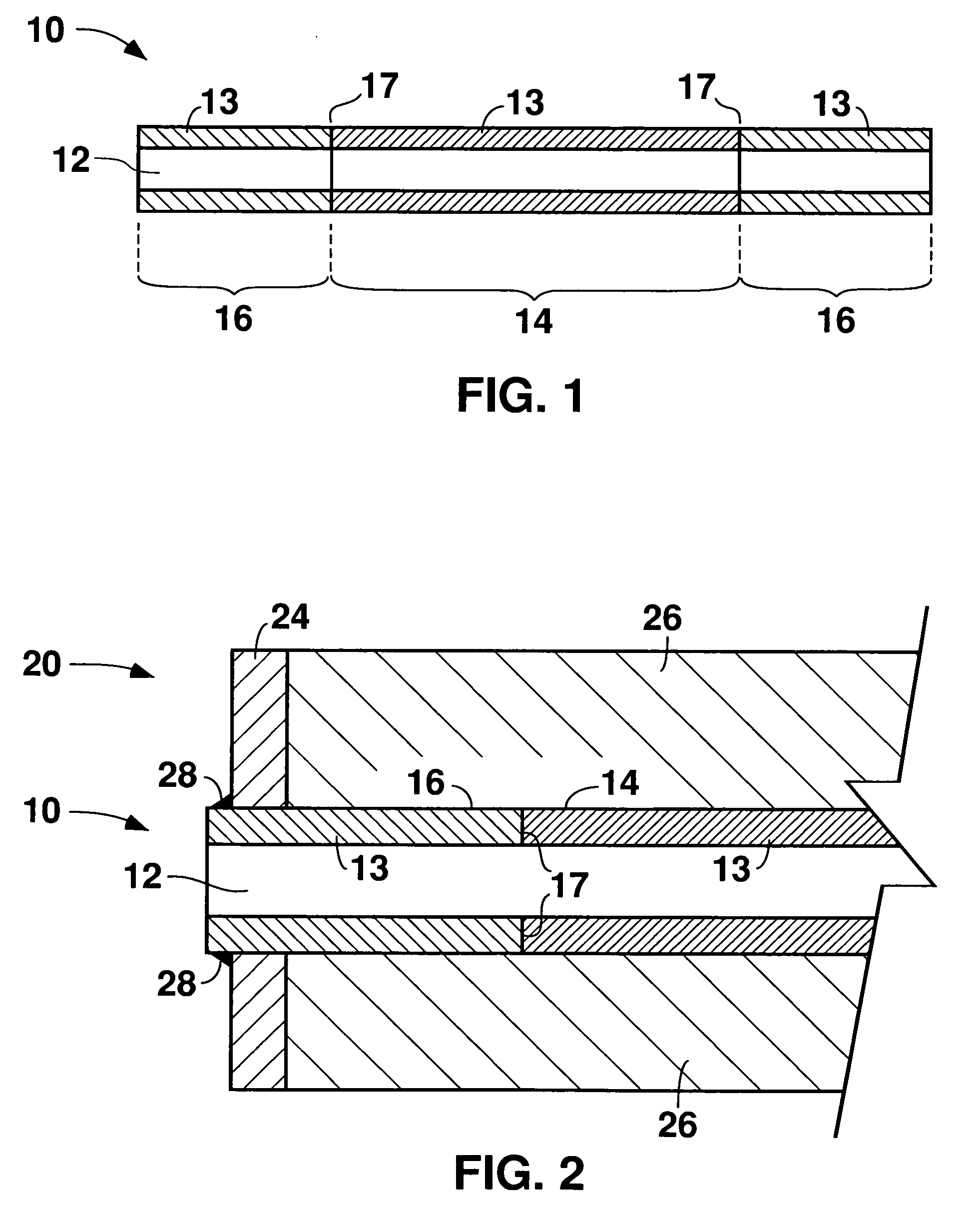
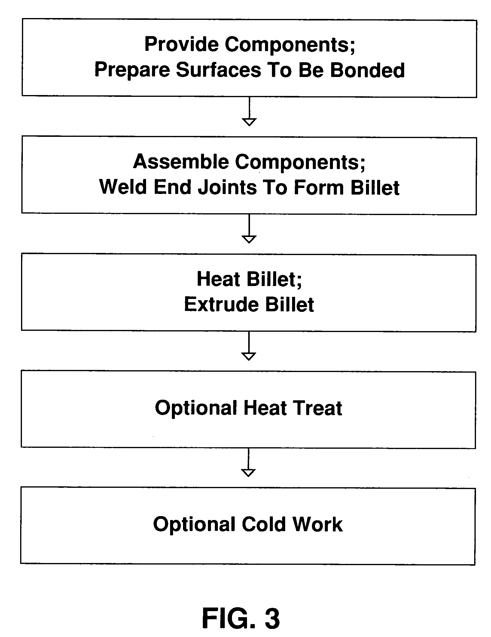
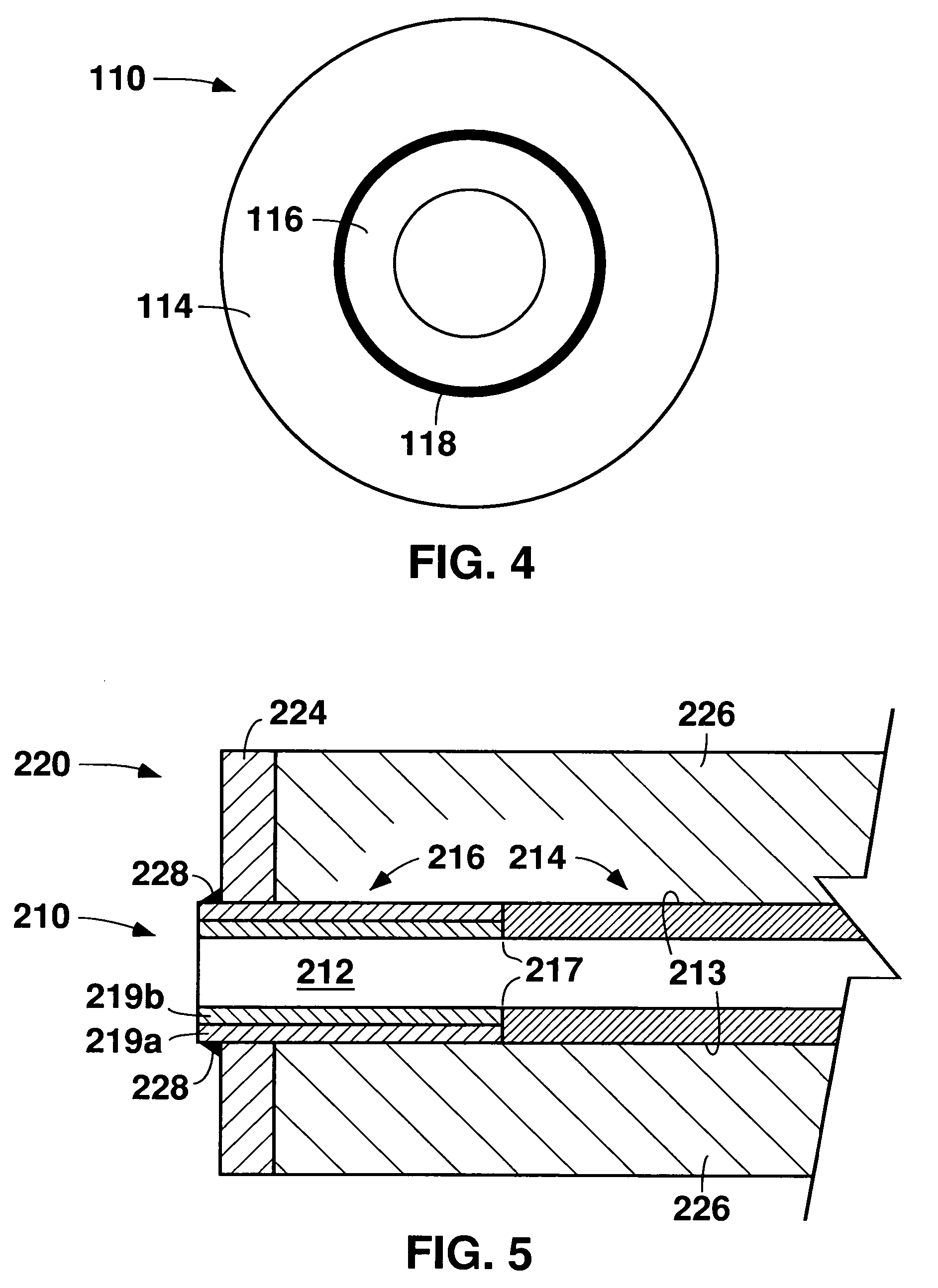
[0123] One embodiment for metallurgically bonding dissimilar reactive metals such as, for example, titanium and zirconium, to form a multi-layer, fluid conducting member involves three distinct process routes. The first process route is directed to fabricating an outer billet, or base component. The second process route is directed to fabricating an inner liner component. In the third process route, the base component and the liner component are combined into an assembled billet, and the billet is then extruded, cold worked, and heat treated to provide the multi-layer tube. In the following paragraphs, the three process routes are described in greater detail as specifically applied in the production of multi-layer tubing including a titanium Grade 3 (UNS R50550) outer base and a Zircadyne 702 (Zr702) (UNS R60702) inner liner. Zr702 alloy is available from ATI Wah Chang, Albany, Oregon, and has the following chemistry (in weight percentages of total al...


PUM

PropertyMeasurementUnit
temperaturesaaaaaaaaaa
pressuresaaaaaaaaaa
lengthaaaaaaaaaa

Abstract

According to one aspect of the present disclosure, a part for an article of equipment includes a fluid conducting first region including a corrosion resistant first material, and a fluid conducting second region including a second material. The first region and the second region are either directly or indirectly joined by solid state welding to form a unitary fluid conducting part. According to another aspect of the present disclosure, a method for replacing at least one fluid conducting part of an article of equipment is disclosed wherein a replacement part is provided that includes a fluid conducting first region including a corrosion resistant first material, and a fluid conducting second region including a second material. The second material is substantially identical to the material of a region of the equipment on which the replacement part is mounted. The first and second regions are either directly or indirectly joined by solid state welding to form a unitary fluid conducting replacement part. The replacement part is secured to the article of equipment by a process comprising fusion welding the second material of the second region of the replacement part to the substantially identical material of the mounting region of the article of equipment.

Description

CROSS-REFERENCE TO RELATED APPLICATIONS [0001] This applications claims priority under 35 U.S.C. § 119(e) to U.S. provisional patent application Ser. No. 60 / 598,228, filed Aug. 2, 2004.BACKGROUND OF THE TECHNOLOGY [0002] 1. Field of Technology [0003] The present disclosure is directed to corrosion resistant fluid conducting parts, methods of making such parts, and equipment including one or more such parts. The present disclosure also is directed to methods of replacing one or more fluid conducting parts of an article of equipment with improved, corrosion resistant fluid conducting parts. The present disclosure is further directed to articles from which corrosion resistant fluid conducting parts can be formed. [0004] 2. Description of the Background of the Technology [0005] Various industrial processes and equipment operate at very high pressures and temperatures. For example, throughout the world the industrial scale process for synthesizing urea involves the reaction of ammonia an...

Claims


Application Information

Patent Timeline
Patent Type & Authority Applications(United States)
IPC IPC(8): A47J36/02
CPCB01J19/02B01J19/2415B01J2219/0236B01J2219/0277Y10T428/12292F28F11/00F28F19/06F28F2275/062Y10T29/4935F28F9/18B24C1/003B21C23/085B21C23/22B23K20/10B23K20/129B23K20/233Y10T428/31808B23K2103/05B23K2103/08B23K2103/14B23K2103/18B23K15/04B23K31/027C22F1/183C22F1/186Y02P20/141B23K13/01B23K15/0006F16L9/18H05B6/10
Inventor SUTHERLIN, RICHARD C.HERB, BRETT J.GRAHAM, RONALD A.
Owner ATI PROPERTIES LLC
Why Eureka
Try Eureka