Method and apparatus for acoustically controlling liquid solutions in microfluidic devices

a microfluidic device and liquid solution technology, applied in the direction of fluid speed measurement, fluid speed measurement, energy-based chemical/physical/physico-chemical processes, etc., can solve the problems of difficult to actively mix or control fluid flow in small quantities, microfluidic devices, and the detrimental effect of diffusion-based systems on commercial products, etc., to achieve the effect of accelerating molecular interactions and improving reaction rates

Inactive Publication Date: 2006-02-09
COVARIS INC
View PDF61 Cites 64 Cited by
  • Summary
  • Abstract
  • Description
  • Claims
  • Application Information

AI Technical Summary

Benefits of technology

[0242] One advantages of the mixing technology of the invention is that by locating or making use of cavitation features close to the edges or margins of the chamber of conduit, with the invention the highest fluid flow velocities are achieved at those locations. Other methods which provide bulk fluid flow cause the highest velocities to occur near the center of the chamber or conduit where they are less useful for applications such as flushing or reacting solution phase molecules with those bound to a surface. Another advantage of the methodology of the invention is that mixing can be achieved in a rigid microdevice. Other technologies require that the chamber or conduit to be mixed have a flexible member (such as a plastic film contacting a liquid fluid or an aqueous / organic liquid fluid interface) that can be deflected by external means to cause bulk fluid motion within the device. No such flexible member is required with the invention. A further advantage of the invention is that nucleation sites or textures can be built into a microdevice such that mixing or fluid flow occurs only in desired locations. This is useful for controlling the extent and location of high velocity flows that may have a detrimental effect on sensitive areas within the device.
[0243] Another advantage of the invention is that it can operate either as an integrated component of a microdevice or as a separately fabricated, but acoustically coupled add-on. In a further embodiment of the invention, the localized bubble formation and collapse created by the interaction of the acoustic field 240 with nucleation features can be employed to clean electrodes in a microdevice. One of the difficulties of performing electrophoresis in a miniaturized format is the scaling effects of miniaturization. Another difficulty is the presence of bubbles. Bubble-effects can block internal lumen, thereby rendering a sample / chip invalid. Another limitation is the intrinsic properties of the electrophoresis process; namely, the generation of bubbles from the electrolysis of water at noble metal electrodes. This bubble formation may have detrimental effects in miniaturized formats by blocking fluid flow, and by affecting the efficiency of the electrophoresis by limiting the current. Cleaning the electrodes can minimize some of these difficulties. The invention may also be used to sweep across the electrophoresis zone to mechanically agitate the molecules to be separated.
[0244]FIGS. 16A and 16B are conceptual block diagrams depicting a micro-electrode cleaning device according to an illustrative embodiment of the invention. The microdevice 1602 is composed of two elements 1004 and 1006 arranged to form a chamber or conduit 1608. The element 1604 includes a nucleation promoting feature 1610. An electrode 1612 is mounted on the element 1606 and includes an electrically conductive lead 1614. The chamber 1608 contains a liquid fluid. By causing a bubble 1616 to form and collapse using the methods described above, the mixing apparatus of the invention can be employed to clean the electrode 1012.
[0245]FIG. 17 depicts another embodiment in which bubble nucleation is facilitated by electrolysis at an electrode. An electrical current is applied via a connection 1706 to an electrode 1704 mounted on a substrate 1702 and in contact with a fluid medium 1708 such that hydrogen (or other gas) bubble(s) is generated. Growth of the bubble may be either by continued generation of gas by electrolysis or by subsequent interaction with the acoustic field 240. In the presence of an appropriate acoustic field 230, the bubble(s) will grow, release from the nucleation site and stream in response to gradients in the acoustic field. The size of the electrolysis bubbles and the frequency of their occurrence can be controlled by the electrical signal to the electrode 1704. Many bubbles may be generated on an electrode 1704 or many individual electrodes 1704 or conductive sites may be employed. Nucleation may be controlled by means of electrical signals applied to the sites rather than by an acoustical source. This method may be used to cause controlled nucleation of cavitation events at specific locations or in specific regions at specific times without the microdevice being movable relative to the acoustic source 230. For example, a device may have an integrated non-focused acoustic source 230. Bubble streaming and fluid flow can be activated in specific regions of the microdevice as required by controlled activation of electrodes 1704 in the regions. Acoustic field gradients may be pre-established by the deployment of absorptive or reflective materials, either between the acoustic source 230 and the fluid volume 1708, or on the far side of the fluid volume 1708, relative to the acoustic source 230, so as to influence either incident or reflected acoustic radiation.
[0246]FIG. 18 is a conceptual diagram depicting an acoustic based mixing apparatus that incorporates the acoustic source into a microfluidic device according to an illustrative embodiment of the invention. FIG. 18 shows a cross-section of a microfluidic device 1800 with an acoustic source 1890 which is connected to an electronic controller (not shown) by connections 1870 and 1880. The device 1800 also includes nucleation promoting features 1850 which may be located in the microdevice opposite the acoustic source as shown or on the surface of the source itself. As shown in the figure, the acoustic energy drives oscillation of a gas body or bubble 1810 in a fluid 1812 contained within a microchamber or microconduit formed by the two structures 1840 and 1845 provides a local micromixing action around the features 1850 indicated by the arrows 1820. The acoustic source can also cause fluid motion by streaming of bubbles as shown in FIG. 13.
[0247] The acoustic source 1890 can form an entire internal surface of the microdevice, can form a portion of an internal surface of the microdevice or can be attached to an internal surface of the device. The acoustic source 1890 can be integrally fabricated with the microdevice or may be separable from the microdevice so as to be reusable. A thin film or membrane 1846 may separate the integrated acoustic source 1890 from the fluid 1812. The membrane 1846 may be tailored to facilitate or block the transmission of the acoustic energy from the acoustic source 1890 into the fluid 1812 in selected areas.

Problems solved by technology

It is difficult to actively mix or control fluid flow in small, microfluidic devices.
The detrimental effects of having a diffusion-based system on commercial products are numerous, such as but not limited to a constraint on reducing assay times and difficulty in actively controlling intra-assay precision and accuracy.
The transducer contacts the sample fluid directly, which severely limits practical applications, particularly with microfluidic devices.
Moreover, when cavitation bubbles formed in older devices collapse, the bubble nucleation, growth and collapse is not directed, nor controlled device.

Method used


Image

  • Method and apparatus for acoustically controlling liquid solutions in microfluidic devices
  • Method and apparatus for acoustically controlling liquid solutions in microfluidic devices
  • Method and apparatus for acoustically controlling liquid solutions in microfluidic devices

Examples


example one

Cavitation Promoting Sites

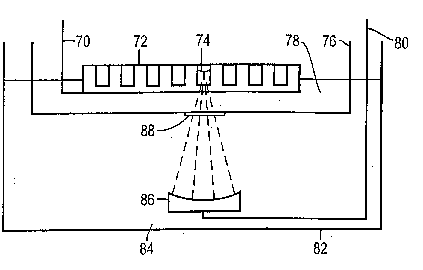
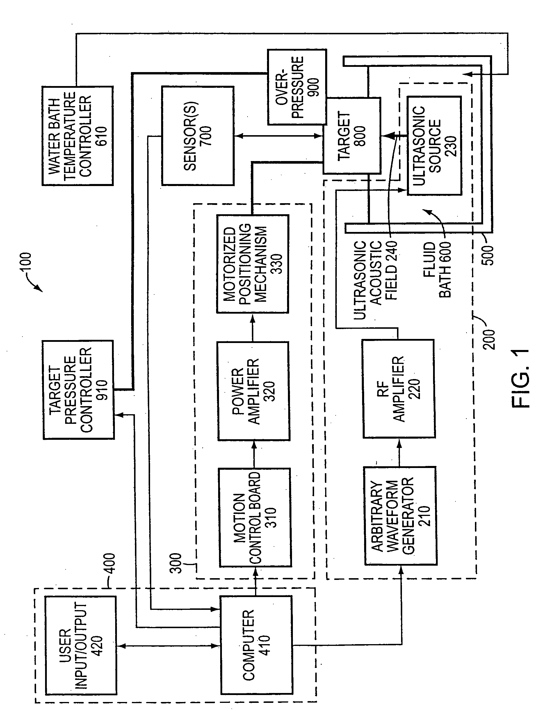
[0263] A glass slide was scratched with a diamond scribe. The slide was placed in a slide holder and installed scratch-down in the apparatus of FIG. 1, modified by the addition of a 5 MHz cavitation detection transducer placed confocally with the main 1.1 MHz acoustic power transducer 230. This instrument was used for all the following examples except where noted. A process was configured to sweep the slide through the focal point of the convergent acoustic beam of the power transducer. The glass slide was insonified with a treatment waveform generated by a 100 mV, 1% duty cycle, 1000 cycles per burst signal applied to a 55 dB RF amplifier and input to the power transducer. Both the input signal to the RF amplifier and the output signal from the cavitation detection transducer were applied to channels 1 and 2 of a Tektronix TDS 30334 digitizing oscilloscope. The signal from the cavitation detection transducer was processed in real time to create a FFT freq...

example two

Mixing With Particles in a Acoustic Field

[0266] We conducted a number of experiments with dyes and water in a chamber on a microscope slide. The chamber was 12 mm in diameter and 0.5 mm high. We applied dye and water in the chamber and placed it in a sample holder, such as those described above with respect to FIGS. 1-7. We adjusted the water level in the tank such that the top of the slide was not covered by water. This creates a standing-wave sound field when insonified from below. We insonified the chamber with a wide range of treatments. These treatment caused noticeable but not dramatic mixing. We then added glass microspheres of the type used to thicken epoxy to the chamber. In the standing-wave acoustic field, the microspheres translated and aggregated at the acoustic nodes. By dithering the chamber in two dimensions in the acoustic field, the particles were forced to translate within the chamber and thus, mix the fluid in the chamber. We noticed a significant increase in mi...

example three

Selectively Blocking an Acoustic Field

[0267] If a microdevice or region to be treated is smaller than the focal region of a convergent acoustic beam, or if it is necessary to protect portions of the microdevice from the sound field, acoustic blocking materials may be placed to shadow selected areas from the acoustic source. To illustrate this and its application to MEMS devices, an acoustic blocking material (Tyvek) was applied to the outside of a chamber containing a piece of foil. The result was that cavitation damage preferentially occurs on the unblocked portion of the foil.


PUM

PropertyMeasurementUnit
frequencyaaaaaaaaaa
frequencyaaaaaaaaaa
diameteraaaaaaaaaa

Abstract

Acoustic energy is used to control motion in a fluid. According to one embodiment, the invention directs acoustic energy at selected naturally occurring nucleation features to control motion in the fluid. In another embodiment, the invention provides focussed or unfocussed acoustic energy to selectively placed nucleation features to control fluid motion. According to one embodiment, the invention includes an acoustic source, a controller for controlling operation of the acoustic source, and one or more nucleation features located proximate to or in the fluid to be controlled.

Description

REFERENCE TO RELATED APPLICATIONS [0001] This application claims the benefit of and priority to U.S. Provisional Patent Applications 60 / 243,838, entitled “Method and Apparatus for Microstream Mixing of Liquid Solutions in Micro Fluidic Devices” filed on Nov. 8, 2000, 60 / 198,923, entitled “Method and Apparatus for Microstream Mixing of Fluidic Liquid Solutions” filed on Mar. 28, 2000, and 60 / 191,297, entitled “Method and Apparatus for Microstream Mixing of Fluidic Liquid Solutions” filed on Mar. 21, 2000; and International Patent Application PCT / US99 / 25274, entitled “Apparatus and Methods for Controlling Sonic Treatment” filed on Oct. 28, 1999, which itself claims priority to U.S. Provisional Patent Applications 60 / 105,933, entitled “Cryotripsy: Disruption of Frozen Samples by Sound Waves” filed on Oct. 28, 1998; 60 / 110,460, entitled “Permeabilization of Biological Samples by Sound” filed on Dec. 1, 1998; 60 / 119,500, entitled “Apparatus and Methods for Disrupting a Biological Sample”...

Claims


Application Information

Patent Timeline
Patent Type & Authority Applications(United States)
IPC IPC(8): B01J19/00B01F33/40B81B1/00C40B60/14
CPCB01F3/08G10K15/00B01F11/0283B01F13/0001B01F13/0059B01F13/02B01F13/0222B01F15/00123B01F15/00285B01F15/0201B01F2215/0037B01F2215/0073B01F2215/0427B01F2215/0431B01F2215/045B01F2215/0454B01F2215/0468B01F2215/0477B01J19/0046B01J19/008B01J19/0093B01J19/10B01J2219/00308B01J2219/00315B01J2219/00317B01J2219/00486B01J2219/00495B01J2219/00659B01J2219/00722B01J2219/00783B01J2219/00889B01L3/50273B01L3/5085B01L7/52B01L2400/0433B01L2400/0436C40B60/14B01F11/02B01F23/40B01F31/80B01F31/87B01F33/05B01F33/30B01F33/403B01F33/40B01F35/20B01F35/2202B01F35/71B01F2101/23B01F2101/44
Inventor LAUGHARN, JAMES A. JR.GARRISON, BREVARD S.
Owner COVARIS INC
Why Eureka
Try Eureka