Clustering techniques for faster and better placement of VLSI circuits

a technology of clustering and circuits, applied in computer aided design, program control, instruments, etc., can solve the problems of large number of cells, difficult to achieve physical design without computer aid, and large number of connections between cells, so as to facilitate the placement of designs, reduce the number of objects, and improve the scalability of placement routines

Inactive Publication Date: 2006-02-09
GLOBALFOUNDRIES INC
View PDF12 Cites 17 Cited by
  • Summary
  • Abstract
  • Description
  • Claims
  • Application Information

AI Technical Summary

Benefits of technology

[0015] It is another object of the present invention to provide such a method which enhances the scalability of the placement routines.
[0016] It is yet another object of the present invention to provide a method of designing the physical layout of an IC chip which can effectively reduce the number of objects in a design to facilitate placement in designs having very large numbers of objects.

Problems solved by technology

An IC may include a very large number of cells and require complicated connections between the cells.
Due to the large number of components and the details required by the fabrication process for very large scale integrated (VLSI) devices, physical design is not practical without the aid of computers.
As device technology enters the new deep sub-micron (DSM) era, the role of placement has become more important, and more difficult.
The complexity of IC designs in the DSM realm has been growing significantly mainly due to reduced device sizes.
While these existing placement tools could conceivably be used to find acceptable solutions with more than 10 million objects, it would likely take an unbearably long time to arrive at those solutions.
Thus, current placement tools lack the scalability necessary to handle the ever-increasing number of objects in IC designs.
Unfortunately, performance (i.e., quality assurance) and scalability contradict each other.
Obtaining higher quality placement solutions requires more CPU time.
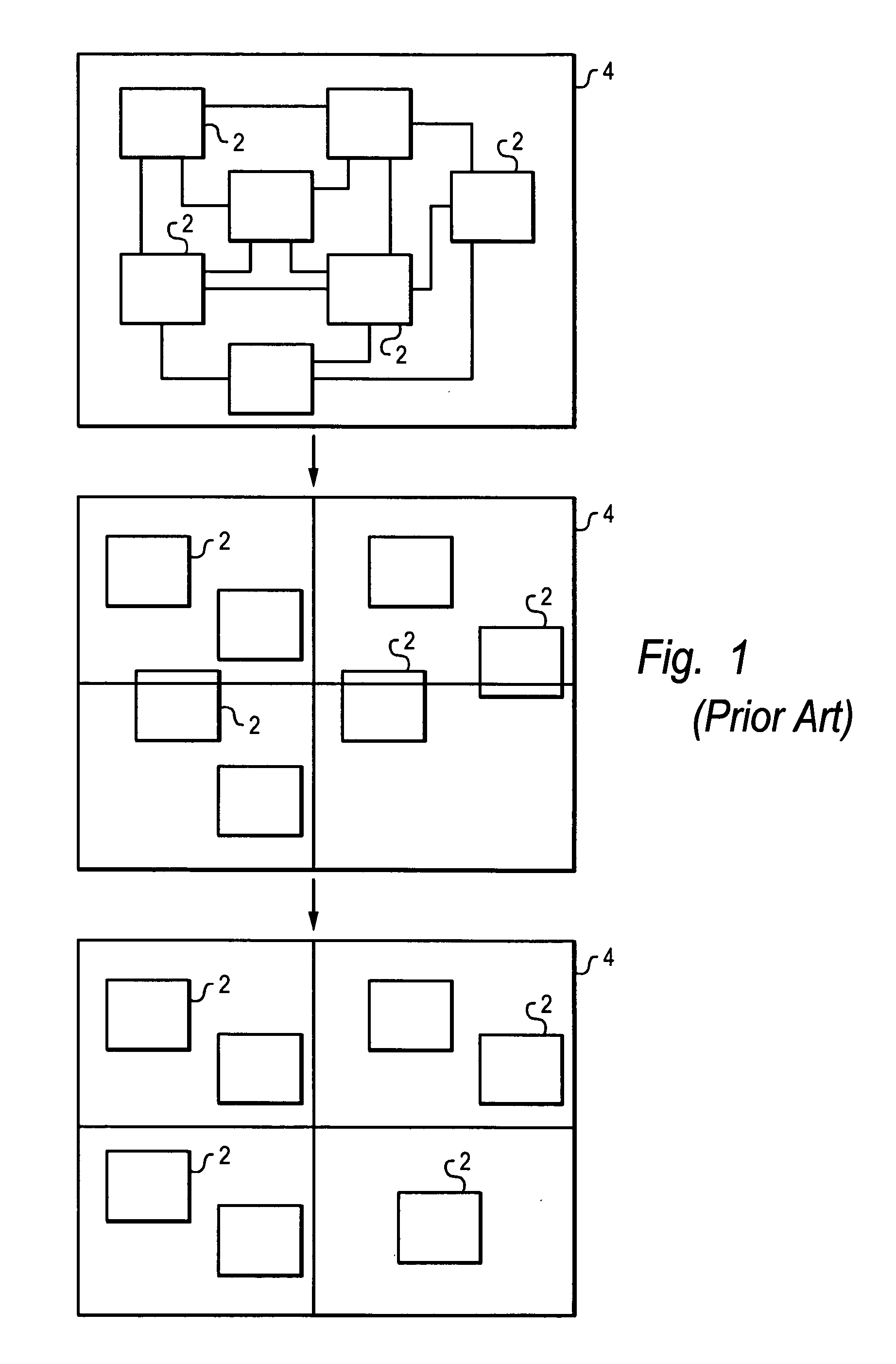
There are, however, several disadvantages to clustering.
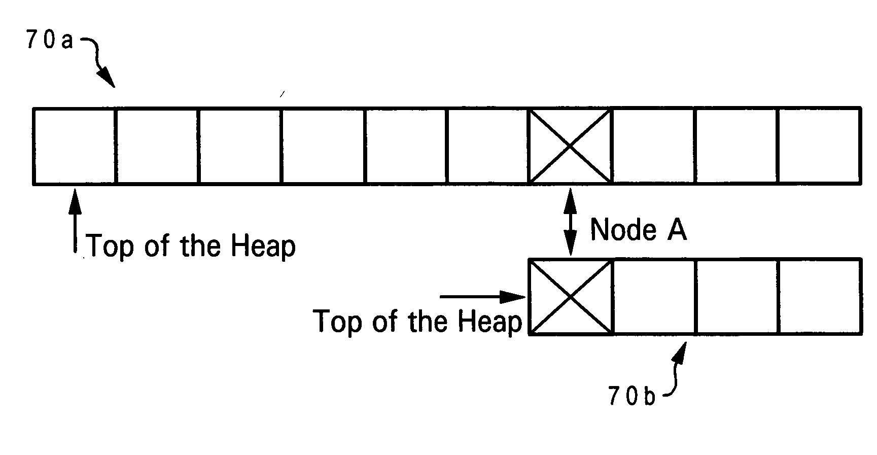
Hypergraph-to-graph transformation (decomposing a hyperedge into a clique) causes a discrepancy in the edge weights once any two objects that belong to same hyperedge are clustered, and leads to an unreasonably large size heap in heap-based implementations.
Pass-based clustering methods such as EC that do not allow object revisiting lead to suboptimal choices since they are likely to forbid an object from clustering to its best neighbor.
Finally, non-heap based implementations such as FC lead to suboptimal clustering choices since a clustered pair of objects might not be the best overall grouping.

Method used


Image

  • Clustering techniques for faster and better placement of VLSI circuits
  • Clustering techniques for faster and better placement of VLSI circuits
  • Clustering techniques for faster and better placement of VLSI circuits

Examples


Embodiment Construction

)

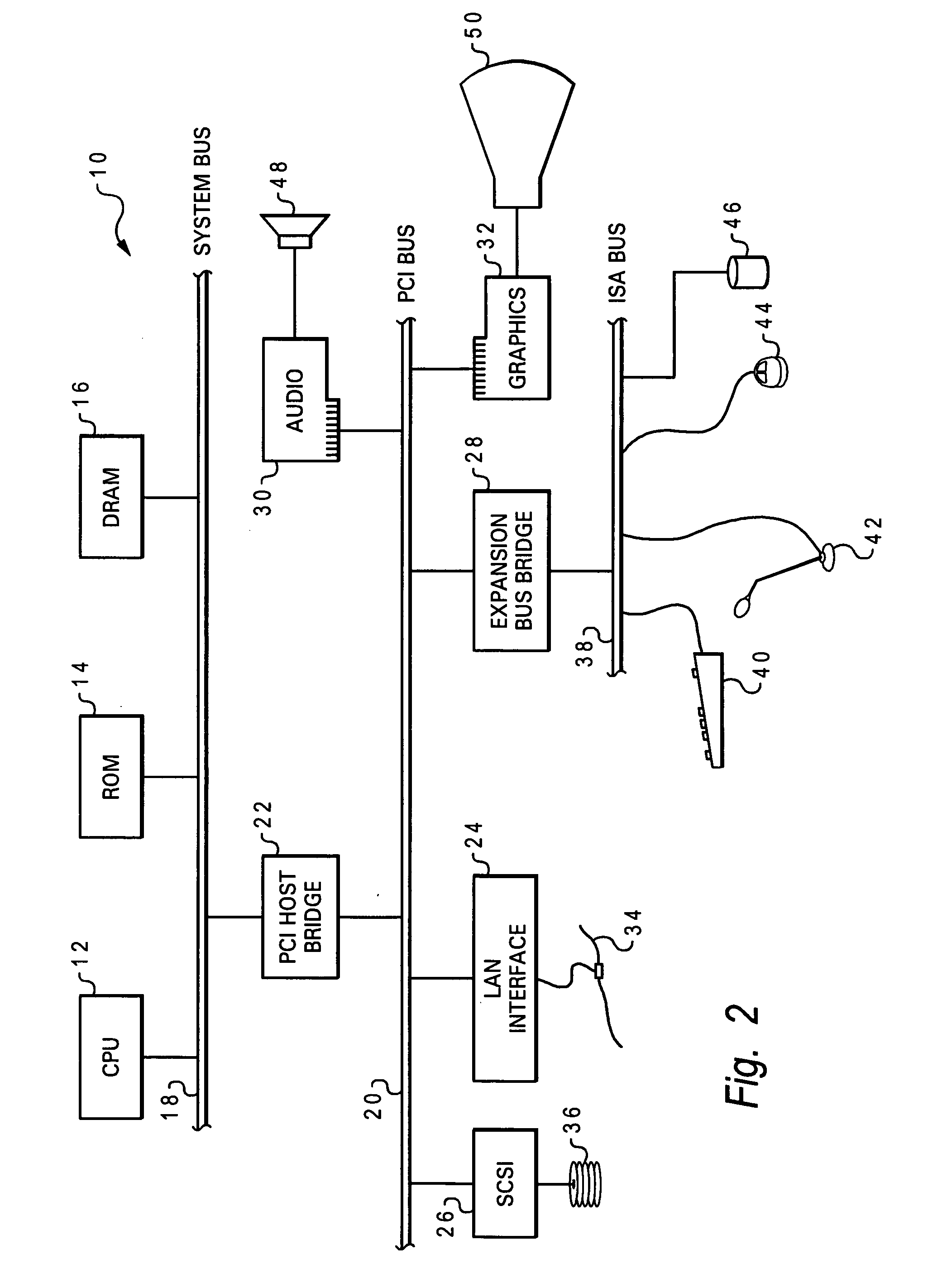
[0027] With reference now to the figures, and in particular with reference to FIG. 2, there is depicted one embodiment 10 of a computer system programmed to carry out computer-aided design of an integrated circuit in accordance with one implementation of the present invention. System 10 includes a central processing unit (CPU) 12 which carries out program instructions, firmware or read-only memory (ROM) 14 which stores the system's basic input / output logic, and a dynamic random access memory (DRAM) 16 which temporarily stores program instructions and operand data used by CPU 12. CPU 12, ROM 14 and DRAM 16 are all connected to a system bus 18. There may be additional structures in the memory hierarchy which are not depicted, such as on-board (L1) and second-level (L2) caches. In high performance implementations, system 10 may include multiple CPUs and a distributed system memory.

[0028] CPU 12, ROM 14 and DRAM 16 are also coupled to a peripheral component interconnect (PCI) local bu...


PUM


Abstract

A placement technique for designing a layout of an integrated circuit by calculating clustering scores for different pairs of objects in the layout based on connections of two objects in a given pair and the sizes of the two objects, then grouping at least one of the pairs of objects into a cluster based on the clustering scores, partitioning the objects as clustered and ungrouping the cluster after partitioning. The pair of objects having the highest clustering score are grouped into the cluster, and the clustering score is directly proportional to the total weight of connections between the two objects in the respective pair. The clustering scores are preferably inserted in a binary heap to identify the highest clustering score. After grouping, the clustering score for any neighboring object of a clustered object is marked to indicate that the clustering score is invalid and must be recalculated. The calculating and grouping are then repeated iteratively based on the previous clustered layout. Cluster growth can be controlled indirectly, or controlled directly by imposing an upper bound on cluster size.

Description

CROSS-REFERENCE TO RELATED APPLICATION [0001] The present application is a continuation-in-part of U.S. patent application Ser. No. 10 / 896,495, entitled “CLUSTERING-BASED MULTILEVEL QUADRATIC PLACEMENT,” filed Jul. 22, 2004, which is hereby incorporated.BACKGROUND OF THE INVENTION [0002] 1. Field of the Invention [0003] The present invention generally relates to the fabrication and design of semiconductor chips and integrated circuits, more specifically to a method of designing the physical layout (placement) of logic cells in an integrated circuit and the wiring (routing) of those cells, and particularly to the use of placement algorithms in designing circuit layouts. [0004] 2. Description of the Related Art [0005] Integrated circuits are used for a wide variety of electronic applications, from simple devices such as wristwatches, to the most complex computer systems. A microelectronic integrated circuit (IC) chip can generally be thought of as a collection of logic cells with elec...

Claims


Application Information

Patent Timeline
Patent Type & Authority Applications(United States)
IPC IPC(8): G06F17/50
CPCG06F17/5072G06F30/392G06F30/398
Inventor ALPERT, CHARLES JAYNAM, GI-JOONREDA, SHERIEF MOHAMEDVILLARRUBIA, PAUL GERARD
Owner GLOBALFOUNDRIES INC
Why Eureka
Try Eureka