Automatic bias control for an optical modulator

an optical modulator and automatic technology, applied in the direction of optical elements, instruments, optical waveguide light guides, etc., can solve the problems of constant readjustment, operating point drift, optical signal interference, etc., and achieve the effect of no loss of transmitted ligh

Active Publication Date: 2006-02-16
LUMENTUM TECH UK LTD
View PDF15 Cites 50 Cited by
  • Summary
  • Abstract
  • Description
  • Claims
  • Application Information

AI Technical Summary

Benefits of technology

[0028] The intensity of light in the difference arm provides a measure of the intensity of the light in the sum arm when integrated over time (i.e. over many bits of the data signal). The frequency of the digital modulation signal (˜102 Hz) is much lower than the frequency of the data signal (˜109 Hz), so over the course of a single period of the digital modulation signal there are millions of bits transmitted. The detection of the intensity of light emitted by the modulator may therefore be achieved by measuring the intensity of light in the difference arm. This means that there is no need to tap the sum arm carrying the modulated light, and thus no loss in the transmitted light.
[0029] Preferably the output of the modulator comprises a multimode interferometer which causes the sum waveform to be transmitted in the sum arm and the difference waveform in the difference arm.

Problems solved by technology

If the path lengths of an unbiased modulator are the same, then at a bias voltage of Vπ the optical signals will interfere destructively and cancel each other out, such that a zero output is produced at the optical output.
However, device instabilities and environmental effects, especially temperature variations, cause the operating point to drift over time, and constant readjustment is required to maintain the proper operating point.
The bias point must be maintained during operation to achieve maximum dynamic range, since second order harmonic distortion increases rapidly with increasing bias voltage error.
This system works well but the tapping of some of the output signal to a photodetector represents optical loss.
Furthermore, the generation of a sinusoidal pilot tone requires hardware which occupies valuable space near the modulator.
The feedback loop also requires a phase sensitive detector and DC coupled amplifiers which are expensive and again occupy valuable space.

Method used


Image

  • Automatic bias control for an optical modulator
  • Automatic bias control for an optical modulator
  • Automatic bias control for an optical modulator

Examples


Embodiment Construction

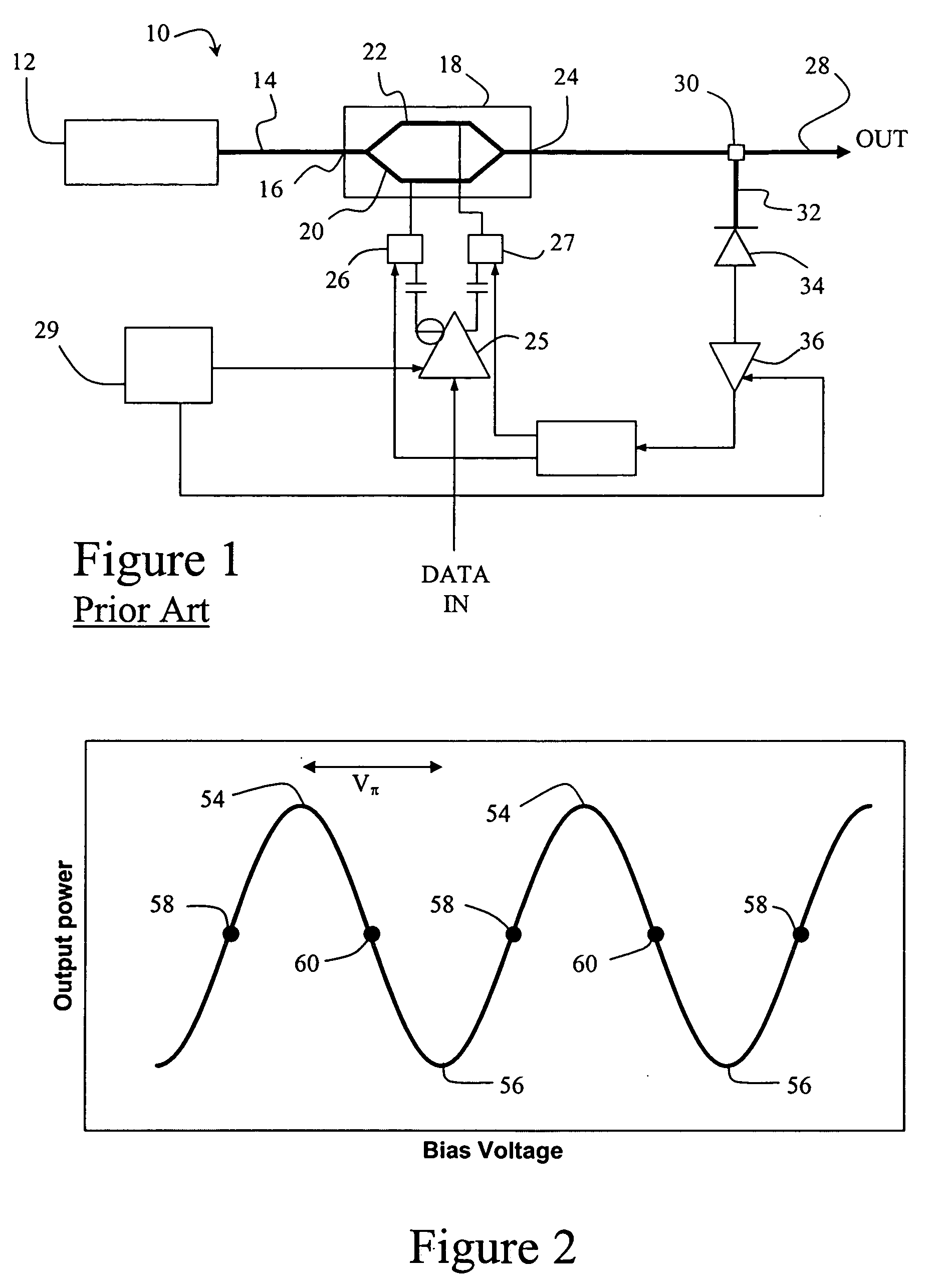
[0046]FIG. 2 is a graph showing how the optical power output of a Mach-Zehnder modulator depends on the relative bias voltage between the arms. It is clear from the figure that, as the bias voltage is increased, the optical power increases and decreases in a periodic manner. The sine curve shown in FIG. 2 has a plurality of peaks 54 and a plurality of troughs 56. Bias points 58 are constituted by positive inflection points in the rising portions of the curve between adjacent troughs 56 and peaks 54, whereas bias points 60 are similarly constituted by negative inflection points between adjacent peaks 54 and troughs 56. The bias points 58, 60 have voltage values approximately half way between those of the peaks 54 and troughs 56, and are the points Vπ / 2 referred to above.

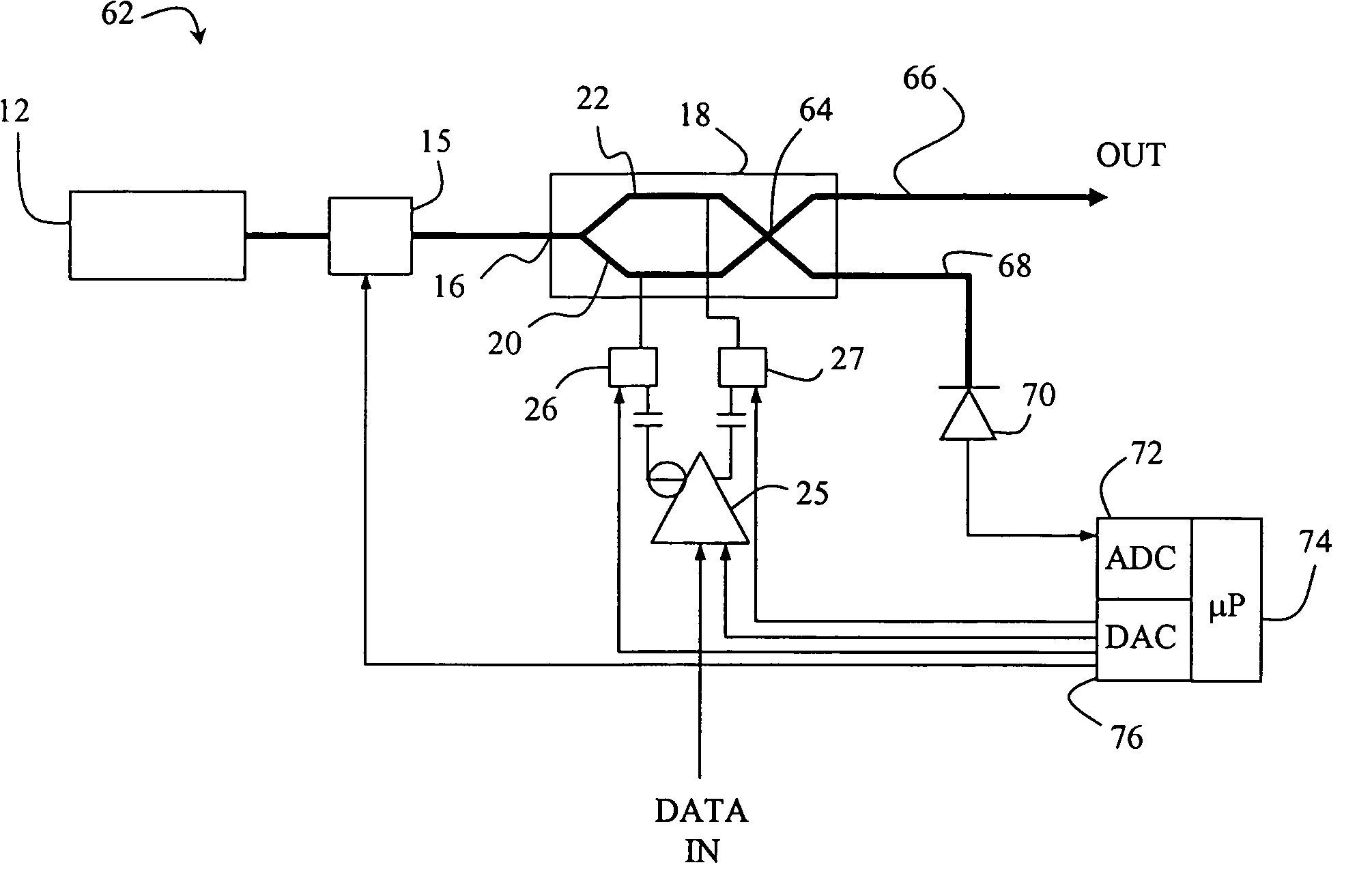
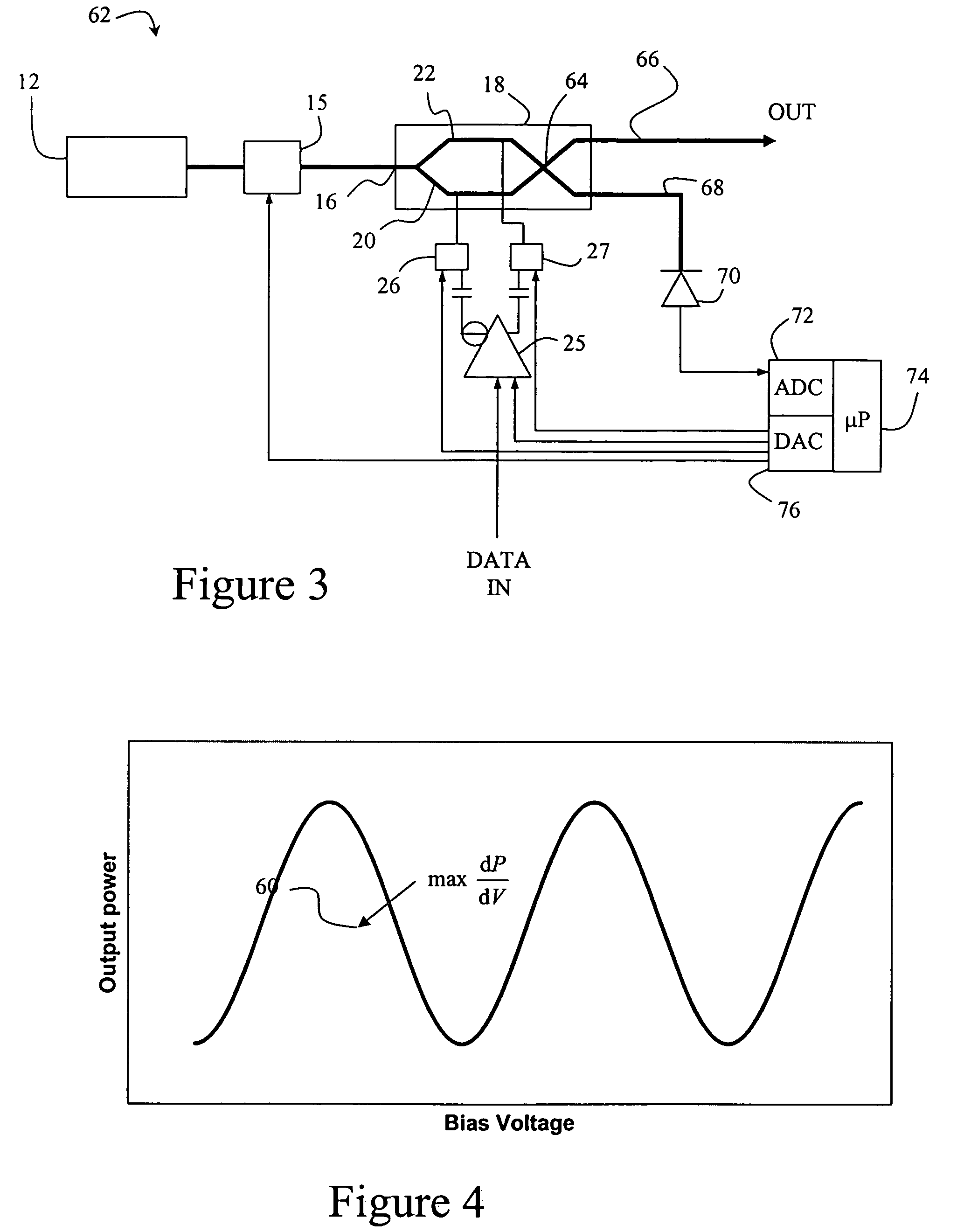
[0047]FIG. 3 is a simplified block diagram of a modulator system 62 in accordance with the present invention. Components similar to those of FIG. 1 are represented by the same reference numerals. A laser 12 feeds a c...


PUM

PropertyMeasurementUnit
frequencyaaaaaaaaaa
frequencyaaaaaaaaaa
frequencyaaaaaaaaaa

Abstract

An automatic bias controller for an optical modulator is provided. The automatic bias controller comprises a driver for providing an electrical data signal to the modulator and bias means for providing a bias voltage to the modulator. A microprocessor provides a low frequency digital modulation signal, which is converted to an analogue modulation signal by a digital to analogue converter. The analogue modulation signal is applied to the bias means (so as to modulate the bias voltage) or to the driver (so as to modulate the amplitude of the data signal). Intensity detection means for detecting the intensity of light emitted by the modulator are provided, and an analogue to digital converter converts the output of the intensity detection means to a digital intensity signal which is passed to the microprocessor. The digital intensity signal is analysed, and the bias means instructed to adjust the bias voltage on the basis of the analysed signal. The digital modulation signal is preferably a rectangular wave or time multiplexed series of periods in which the bias voltage and data signal amplitude are varied.

Description

FIELD OF THE INVENTION [0001] The present invention relates to an automatic bias controller for an optical modulator for use in optical data communications, and more specifically, although not exclusively, to an automatic bias controller for an electro-optic modulator such as a Mach-Zehnder modulator. The invention also relates to an optical transmitter including a modulator with automatic bias control. BACKGROUND OF THE INVENTION [0002] Transmission of data using optical carriers enables very high bandwidths and numbers of multiplexed channels with low signal loss and distortion. A coherent laser light beam is amplitude modulated with a data signal, and propagates to a remote receiver via a system of optical fibres and repeaters. The light beam may advantageously be modulated with electrical signals in the microwave frequency range using an electro-optic modulator such as a Mach-Zehnder modulator or optical coupler. [0003] Mach-Zehnder electro-optic modulators are well known. An el...

Claims


Application Information

Patent Timeline
Patent Type & Authority Applications(United States)
IPC IPC(8): H04B10/04H04B10/12G02F1/01H04B10/50H04B10/58
CPCG02F1/0123H04B10/505H04B10/58H04B10/50575H04B10/50572
Inventor TIPPER, ALAN
Owner LUMENTUM TECH UK LTD
Why Eureka
Try Eureka