Method for manufacturing high pressure discharge lamp, high pressure discharge lamp manufactured using the method, lamp unit, and image display device

a technology of discharge lamp and discharge lamp, which is applied in the manufacture of spark plugs, tube/lamp factory adjustment, electrode system, etc., can solve the problems of shortening affecting the service life of high pressure mercury lamps, and impurities unavoidably entering the discharge space inside the light emitting part, etc., to achieve easy expulsion, facilitate the ionization of impurities, and reduce maintenance costs

Inactive Publication Date: 2006-02-16
PANASONIC CORP
View PDF10 Cites 10 Cited by
  • Summary
  • Abstract
  • Description
  • Claims
  • Application Information

AI Technical Summary

Benefits of technology

[0025] The above method facilitates the ionization of impurities inside the light emitting part, as a result of which the impurities are more easily expelled from the discharge space in the light emitting part by the electric field.
[0026] A high pressure discharge lamp manufactured according to the above method has a long life as the light emitting part is kept from devitrification and blackening. Such a high pressure discharge lamp may be combined with a concave reflecting mirror to form a lamp unit which can then be used as a light source of an image display device. Since this lamp unit need not be replaced frequently, maintenance costs can be reduced.

Problems solved by technology

This causes a leakage of the substances enclosed in the light emitting part 501.
According to these constructions, however, blackening and devitrification tend to occur in the light emitting part during lighting, which shortens the service life of the high pressure mercury lamp.
When manufacturing or lighting the high pressure mercury lamp, such impurities unavoidably enter into a discharge space inside the light emitting part.
This leads to devitrification.
As a result, a halogen cycle cannot work properly, and tungsten evaporating from the electrode deposits itself on the inner wall of the light emitting part.
This leads to blackening.
Efforts have been made to prevent impurities, which are contained in the sealing part having a high pressure-resistance construction, from entering into the light emitting part in the high pressure mercury lamp, but no decisive solution has yet been proposed.
This problem can occur not only in the high pressure mercury lamps but also in high pressure discharge lamps having sealing parts in general.

Method used


Image

  • Method for manufacturing high pressure discharge lamp, high pressure discharge lamp manufactured using the method, lamp unit, and image display device
  • Method for manufacturing high pressure discharge lamp, high pressure discharge lamp manufactured using the method, lamp unit, and image display device
  • Method for manufacturing high pressure discharge lamp, high pressure discharge lamp manufactured using the method, lamp unit, and image display device

Examples


first embodiment

[0059] The inventors of the present invention devised a new construction of a high pressure discharge lamp (including a high pressure mercury lamp) in which a pressure resistance of a sealing part is increased to cope with an increased pressure inside a light emitting part, and thereby succeeded in achieving a higher pressure resistance strength. The inventors filed patent applications based on this construction (Japanese Patent Application No. 2002-351523 and Japanese Patent Application Publication No. 2003-234067).

[0060] This embodiment describes a method for manufacturing such a high pressure discharge lamp having a high pressure resistance strength and especially a high pressure mercury lamp, according to which blackening and devitrification in the light emitting part can be suppressed to thereby increase a lamp life.

(1) Construction of a High Pressure Mercury Lamp

[0061]FIGS. 3A and 3B show a construction of a high pressure mercury lamp (hereafter simply called a “lamp”) 111...

second embodiment

[0132] A lamp manufacturing method according to the second embodiment of the present invention is described below.

[0133] In the second embodiment, the lamp formation step is the same as that of the first embodiment. The only difference from the first embodiment lies in the electric field application step, so that the following explanation focuses on this difference.

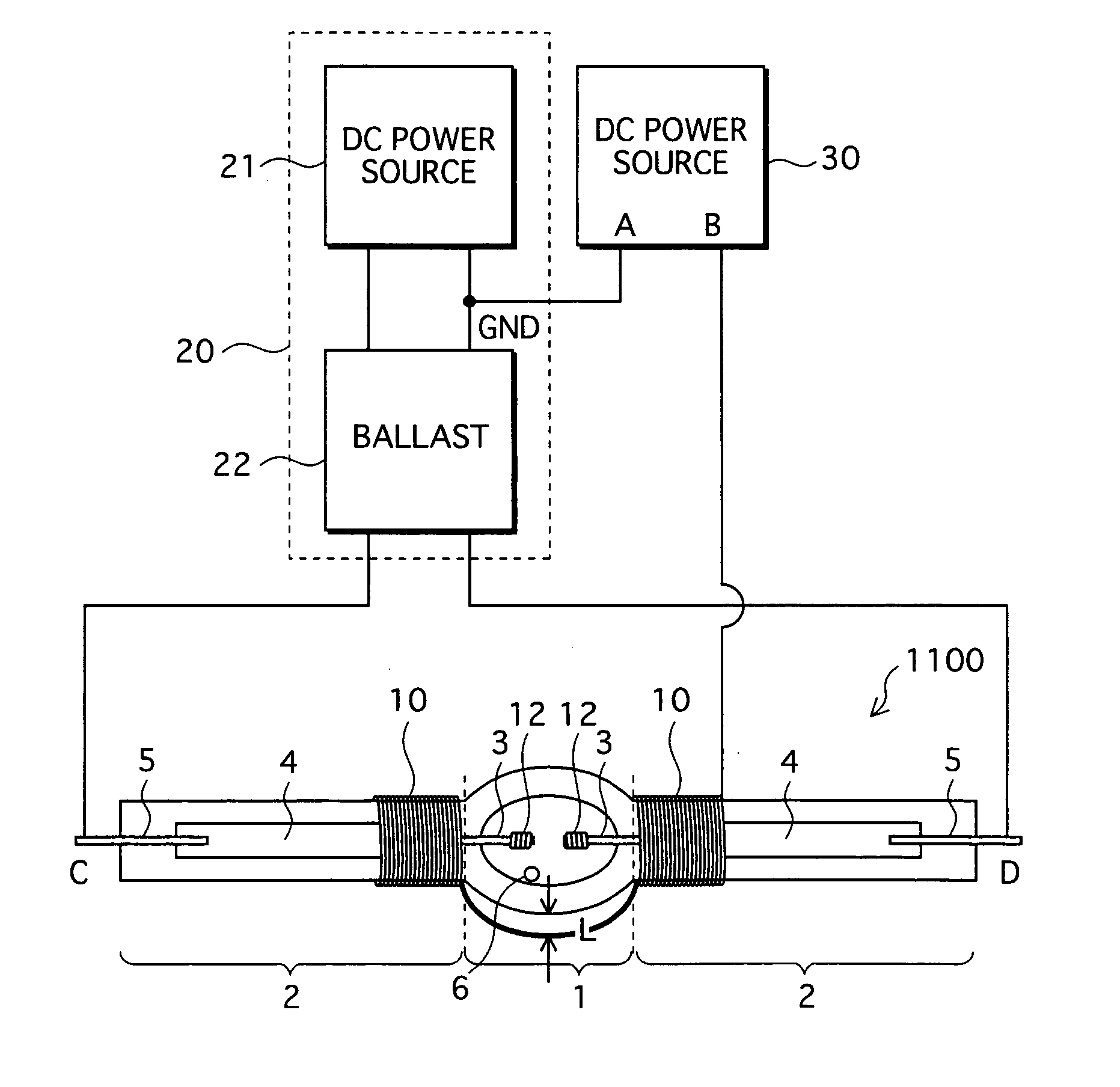
[0134]FIG. 17 shows an electric field application step in the second embodiment.

[0135] After the formation of the lamp 1100, the conductive wire 10 is wound around the sealing parts 2 of the lamp 1100 in the same way as in the first embodiment, prior to initial lighting. The conductive wire 10 is wound around one sealing part, and then wound around the other sealing part across the light emitting part 1. A number of turns in each of the left and right sides is about ten. The distance L between the light emitting part 1 and the conductive wire 10 is about 2 mm. Since the outside diameter of the light emitting part 1 is ...

third embodiment

[0140] The following describes an electric field application step according to the third embodiment of the present invention.

[0141] In the third embodiment, impurities are removed from the glass pipe which is to be formed into the light emitting part 1 and the sealing parts 2, prior to lamp formation.

[0142]FIG. 18 shows the electric field application step in the third embodiment.

[0143] In the drawing, a glass pipe 2000 is a glass pipe for a discharge lamp before manufacturing. The glass pipe 2000 is roughly made up of the scheduled light emitting part 1′ which has a substantially spherical hollow shape, and the tube-shaped side tube parts 2′. A metal rod 2010 is inserted through this glass pipe 2000. The metal rod 2010 is held by a holder (not illustrated) so as to be located substantially at a tube axis of the glass pipe 2000.

[0144] The conductive wire 10 is wound around the pair of side tube parts 2′ of the glass pipe 2000, in the same way as in the first and second embodiment...


PUM


Abstract

A method for manufacturing a high pressure mercury lamp having a high pressure resistance strength includes an electric field application step of applying an electric field to at least a light emitting part while keeping the high pressure mercury lamp at a high temperature. As a result of the electric field application step, impurities such as hydrogen and an alkali metal existing in a discharge space and in glass used for forming the light emitting part (1) and sealing parts (2) can be reduced, with it being possible to suppress blackening and devitrification during lighting.

Description

[0001] This is a continuation of PCT application No. PCT / JP2004 / 003521 filed on Mar. 17, 2004.TECHNICAL FIELD [0002] The present invention relates to a method for manufacturing a high pressure discharge lamp having a high luminous flux maintenance factor and a long life, a high pressure discharge lamp manufactured using this method, a lamp unit, and an image display device. BACKGROUND ART [0003] In recent years, projection-type image display devices such as a liquid crystal projector and a DMD (Digital Micromirror Device) projector are widely used as systems that realize large-screen images. High pressure discharge lamps having high luminance, especially high pressure mercury lamps, are often employed as light sources of such image display devices (see Japanese Patent Application Publication No. H02-148561 as one example). [0004]FIG. 1 shows a construction of a high pressure mercury lamp 1000 disclosed by the above publication. [0005] In the drawing, the high pressure mercury lamp 1...

Claims


Application Information

Patent Timeline
Patent Type & Authority Applications(United States)
IPC IPC(8): H01J9/38H01J9/44H05B41/292
CPCH05B41/2928H01J9/44
Inventor HATAOKA, SHINICHIROTAKAHASHI, KIYOSHISAKAGUCHI, JUNKURIMOTO, YOSHITAKAONO, SYUNSUKETSUTATANI, TAKASHISEKI, TOMOYUKIHORIUCHI, MAKOTOICHIBAKASE, TSUYOSHI
Owner PANASONIC CORP
Why Eureka
Try Eureka