Electromagnetic continuous casting apparatus for materials possessing high melting temperature and low electric conductance

a technology of electric conductance and continuous casting, which is applied in the direction of manufacturing tools, electric/magnetic/electromagnetic heating, and crystal growth process, etc., can solve the problems of increasing manufacturing cost, quality and cost of silicon wafers, and difficulty in making a material, and achieves low electric conductance and high melting point

Inactive Publication Date: 2006-02-23
KCC CORP CO LTD
View PDF2 Cites 18 Cited by
  • Summary
  • Abstract
  • Description
  • Claims
  • Application Information

AI Technical Summary

Benefits of technology

[0013] Therefore, the present invention has been made in view of the above problems, and it is an object of the present invention to provide a convenient electromagnetic continuous casting apparatus for producing a high-purity polycrystalline ingot, in which the heating and melting efficiency of a raw material having a high melting point and a low electric conductance can be remarkably improved, and also the electromagnetic pressure can be maintained higher than the hydrostatic pressure due to the melt height throughout the melt region.

Problems solved by technology

This method has been widely used, but embraces some problems in that the silicon ingot is contaminated by carbon and oxygen introduced from the graphite or quartz crucible, and the quartz crucible is fractured during solidification of silicon and must be replaced with a new one every time to thereby increase the manufacturing cost.
On the other hand, the quality and cost of silicon wafers depend on those of the ingot.
However, since the above conventional electromagnetic continuous casting process uses a water-cooled cold crucible, it has difficulties in making a material, which has a high melting temperature and a low electric-conductivity, a high-purity ingot.
Therefore, a great deal of electric power is required for melting the raw materials.
In particular, since silicon is a semiconductive material having a high melting point and a low electric conductivity, a cooling effect by the emission of radiant heat is high, but, in contrast, the induction heating effect is weak.
Thus, it causes difficulties in melting the silicon material continuously and efficiently.
However, this method leads to a high installation cost and also a high production cost disadvantageously.

Method used


Image

  • Electromagnetic continuous casting apparatus for materials possessing high melting temperature and low electric conductance
  • Electromagnetic continuous casting apparatus for materials possessing high melting temperature and low electric conductance
  • Electromagnetic continuous casting apparatus for materials possessing high melting temperature and low electric conductance

Examples


examples 1 , 2 and 3

EXAMPLES 1, 2 and 3

[0052] The following examples are provided for further understanding of the invention, but not intended to limit the invention.

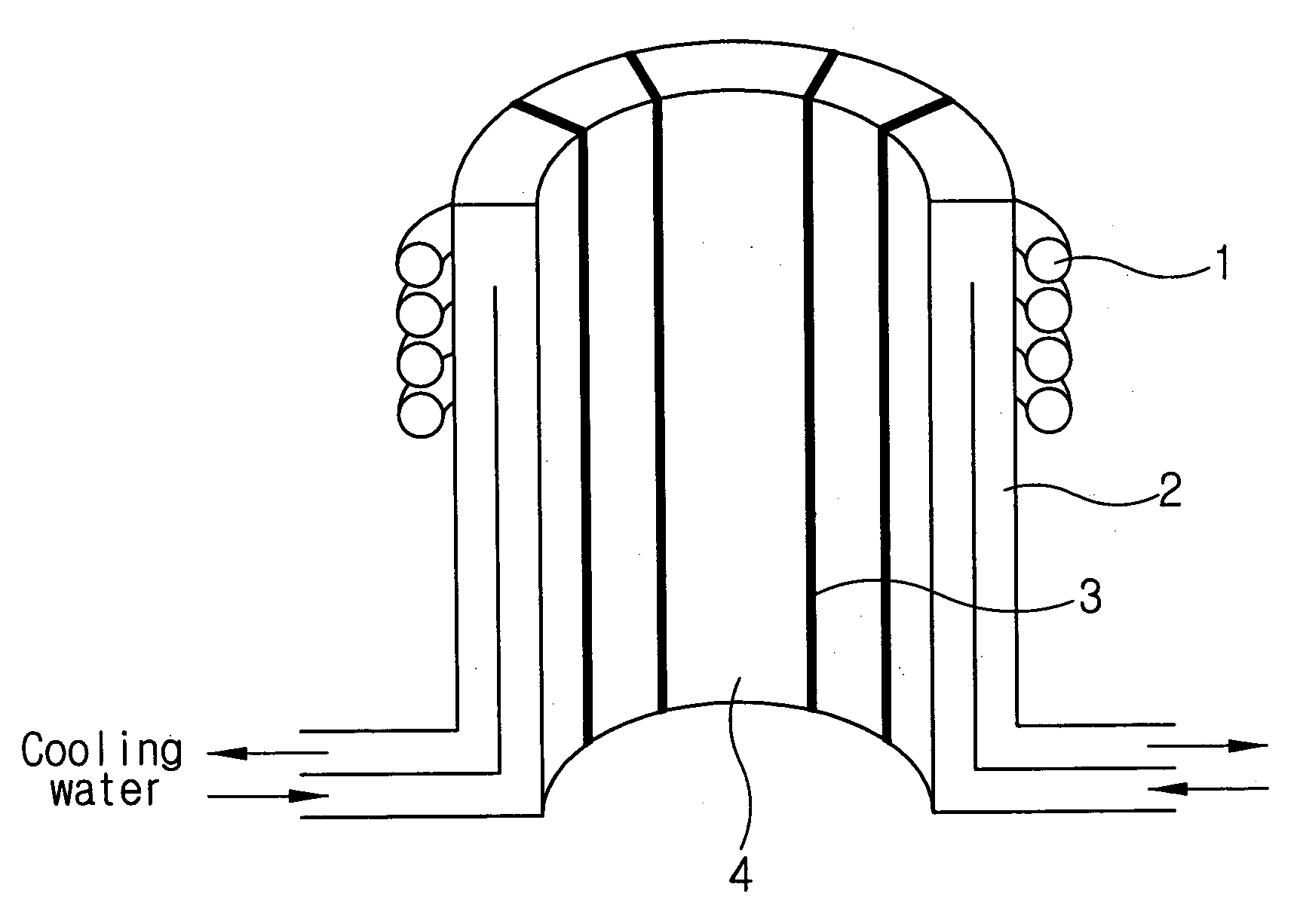
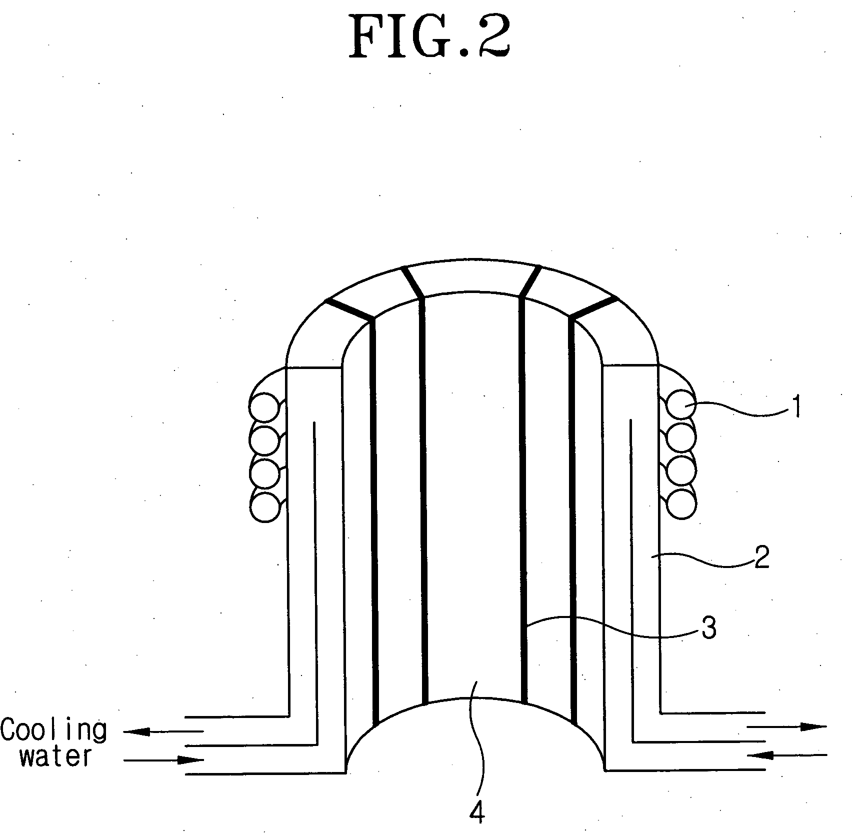
[0053] In the examples 1, 2, and 3, silicon melting and casting experiments have been carried out, respectively using the crucible of first, second, and third embodiment respectively, which are shown FIGS. 3 to 5. The results have been quantitatively compared, in terms of their induction heating effect and electromagnetic pressure effect.

[0054] In all examples, an induction coil 1 of five turns having an inner diameter of 125 mm, an outer diameter of 145 mm, and a height of 54 mm was installed outside of the crucible, in such a way that the top of the induction coil 1 is placed at a distance of 5 mm from the top of the crucible. An alternating current of 20 kHz was applied up to a maximum of 1,230 A.

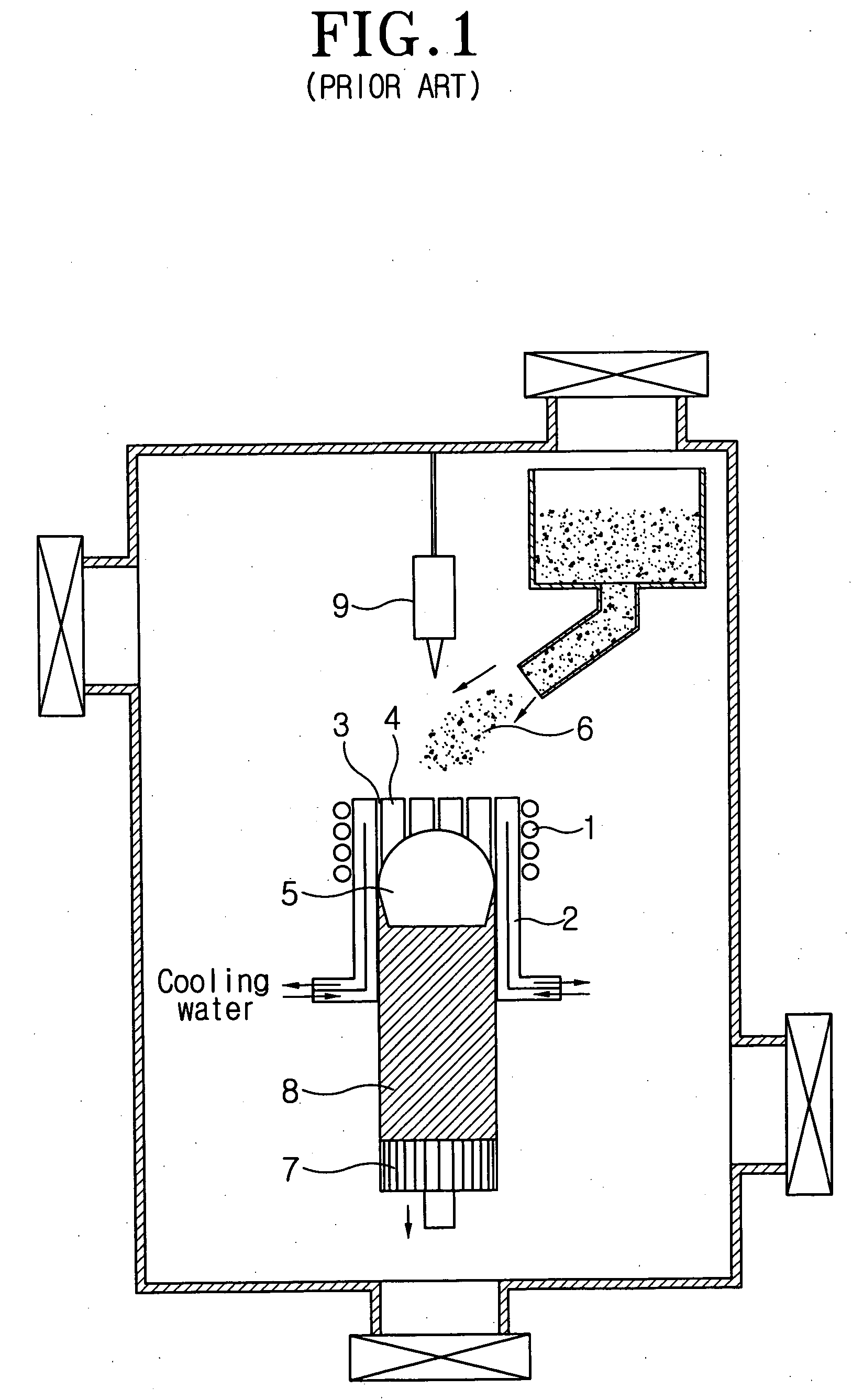
[0055] Referring to FIG. 1, in order to perform a continuous casting, first, a dummy bar 7 was used to close the bottom of the crucible and...


PUM

PropertyMeasurementUnit
thicknessaaaaaaaaaa
heightaaaaaaaaaa
outer diameteraaaaaaaaaa

Abstract

Disclosed is an electromagnetic continuous casting apparatus for a material having a low electric conductivity. The casting apparatus includes a crucible having a vertical axis. The crucible comprises an upper hot crucible and a lower cold crucible. The crucible is surrounded with an induction coil. The hot crucible is formed of a non-metallic material having a high electric conductivity and is not water-cooled. The cold crucible has a cooling structure and is formed of a metallic material having a high thermal conductivity and a high electric conductivity.

Description

BACKGROUND OF THE INVENTION [0001] 1. Field of the Invention [0002] The present invention relates to an electromagnetic continuous casting apparatus for producing a high-purity polycrystalline ingot of semiconductive materials or metallic materials having a high melting temperature and a low electric conductance such as a silicon ingot used for a solar cell substrate. [0003] 2. Background of the Related Art [0004] In general, the aforementioned type silicon ingot is used as a starting material for manufacturing silicon wafers, for example, which are used as photovoltaic elements such as solar cells. [0005] Conventionally, in order to manufacture a polycrystalline silicon wafer for solar cells, firstly, silicon is melted inside a graphite crucible or inside a quartz crucible placed inside a graphite crucible. Thereafter, an ingot is produced by slowly cooling the mold (or crucible) from the bottom thereof such that the melt can be directionally solidified. The ingot is sliced into wa...

Claims


Application Information

Patent Timeline
Patent Type & Authority Applications(United States)
IPC IPC(8): B22D27/02B22D11/00
CPCB22D11/0401B22D11/115C30B11/003C30B11/001C30B11/002C30B29/06C30B15/10C30B15/12
Inventor MON, BYOUNG MOONLEE, SANG MOKSHIN, JE SIK
Owner KCC CORP CO LTD
Why Eureka
Try Eureka