Adaptive gate drive voltage circuit

a gate drive voltage and voltage circuit technology, applied in the direction of instrumentation, process and machine control, pulse technique, etc., can solve the problems of reducing the overall system efficiency of the light load, reducing the efficiency of the overall system, and only working well known gate drive voltage tuning techniques to minimize power loss. , to achieve the effect of preventing unwanted noise, reducing power loss, and improving efficiency

Active Publication Date: 2006-02-23
INFINEON TECH AMERICAS CORP
View PDF4 Cites 52 Cited by
  • Summary
  • Abstract
  • Description
  • Claims
  • Application Information

AI Technical Summary

Benefits of technology

[0019] The invention thereby provides several advantages. For example, efficiency is improved at light loads while maintaining switching frequency, preventing unwanted noise due to hysteretic mode behavior. Also, an optimized gate drive voltage can be automatically generated for all output current conditions, effectively reducing power loss.

Problems solved by technology

A key challenge at this power level is to reduce power loss to keep system efficiency as high as possible, given other system constraints such as board area, cost, etc.
However, this known technique of tuning the gate drive voltage to minimize power loss only works well at one load current and is typically set at the maximum output load.
In applications where the load current can drop to a very low percentage of full load current, the conduction power loss also decreases rapidly, but the switching power loss still burdens the converter, effectively reducing the overall system efficiency in this lighter load condition.

Method used


Image

  • Adaptive gate drive voltage circuit
  • Adaptive gate drive voltage circuit
  • Adaptive gate drive voltage circuit

Examples


Embodiment Construction

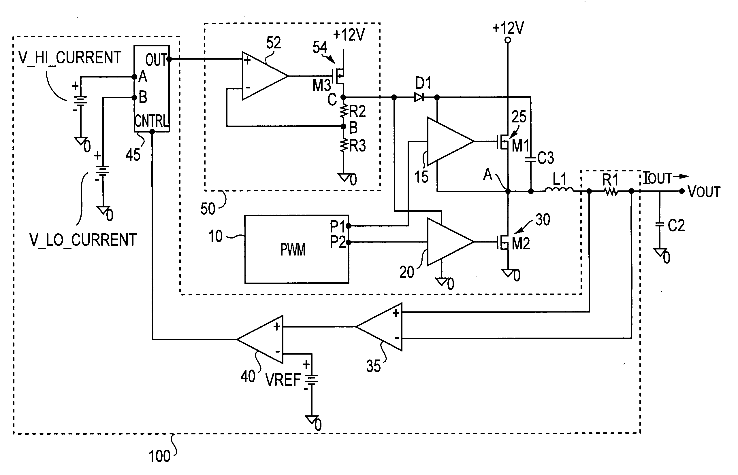
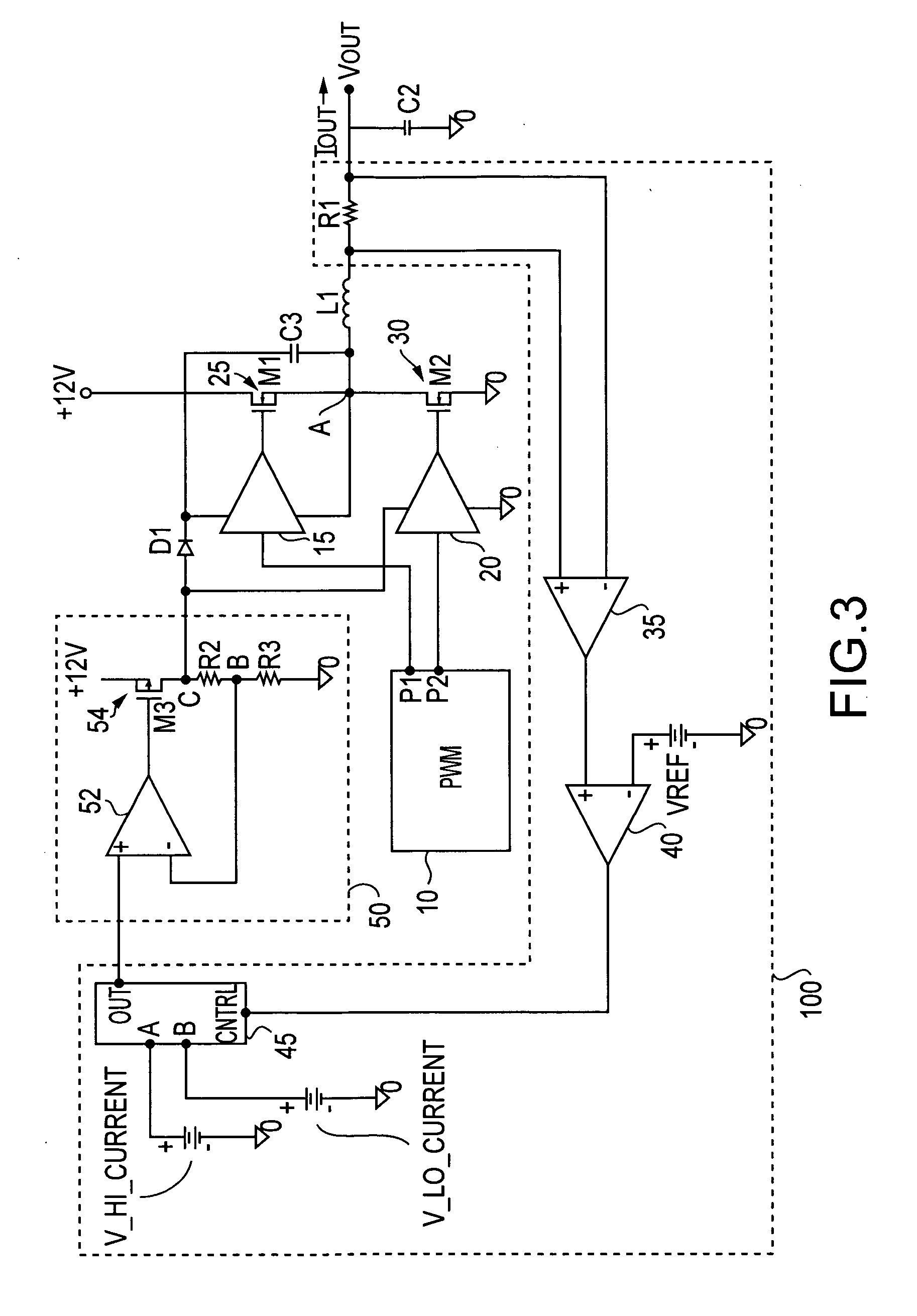
[0026] A DC / DC converter having an adaptive gate drive voltage circuit 100 is shown in FIG. 3. The converter comprises a PWM controller 10 with outputs P1, P2 for controlling the high side gate driver 15 and the low side gate driver 20. The driver 15 drives an N-channel power MOSFET M1 (25) and the driver 20 drives a N-channel power MOSFET M2 (30). The MOSFETs M1 and M2 are connected in a totem-pole arrangement, delivering the output of the converter at a node A therebetween. Also shown are a bootstrap diode D1, a bootstrap capacitor C3, a filtering inductor L1, and a filtering capacitor C2.

[0027] The foregoing components and their operation are conventional and will be well known to those conversant with this art.

[0028] The output current from the node A is sensed in this example by a sense resistor R1 in series with the output inductor. The voltage developed across this resistor is sensed by an amplifier 35. The output of this amplifier is a voltage proportional to the output cu...


PUM


Abstract

A circuit and method for reducing losses in a DC/DC converter by optimizing gate drive voltage. The circuit and method detect a change in the output load, or more specifically the output current, and adjust the gate voltage accordingly; in other words, providing adaptive gate drive voltage. In response to a reduction of output current, the invention reduces the gate voltage so as to reduce both conduction and switching losses in the semiconductor switching devices in the output stage.

Description

CROSS REFERENCE TO RELATED APPLICATION [0001] The present application is based upon and claims priority of U.S. Provisional Application Ser. No. 60 / 603,814 filed Aug. 23, 2004, incorporated by reference in its entirety.BACKGROUND OF THE INVENTION [0002] 1. Field of the Invention [0003] The present invention relates to a DC / DC converter, and more particularly to a DC / DC converter including a circuit for driving the gates in the output stage adaptively as a function of output current. [0004] 2. Related Art [0005] DC / DC converter designs today are supporting very high output currents of greater than 100A. A key challenge at this power level is to reduce power loss to keep system efficiency as high as possible, given other system constraints such as board area, cost, etc. One technique that has been used to improve efficiency in these systems is to adjust the gate drive voltage to minimize the combination of switching loss and conduction loss in the converter. [0006] A known DC / DC power...

Claims


Application Information

Patent Timeline
Patent Type & Authority Applications(United States)
IPC IPC(8): G05F1/40
CPCH02M1/08H03F3/217H03K2217/0036H03K17/0822H03K17/6871H03K17/063
Inventor AHMAD, FAISAL
Owner INFINEON TECH AMERICAS CORP
Why Eureka
Try Eureka