Display panel inspection apparatus and display panel inspection method

Inactive Publication Date: 2006-02-23
PIONEER CORP +1
View PDF8 Cites 21 Cited by
  • Summary
  • Abstract
  • Description
  • Claims
  • Application Information

AI Technical Summary

Benefits of technology

[0009] The present invention has been accomplished in order to solve the foregoing problem, and it is an object of the invention to realize an improved inspection within a reduced space, at a low cost and a high productivity, and when

Problems solved by technology

However, during an inspection performed by the above-described conventional display panel inspection apparatus, a high miniaturization and a large size screen of a display panel will bring about an existence of a large amount of measurement information.
On the other hand, as mentioned above, since there are many inspection items such as brightness uniformity, luminescent spot, color un-uniformity, pixel defect and margin test, a considerable amount of time is needed for the data processing unit to process image measurement data obtained by the CCD camera.
As a result, the above process greatly affects the tact time of the display panel inspection apparatus, making it impossible to perform an inspection with a high productivity.
Moreover, in order to meet a requirement in production time in manufacturing display panel and realizing an inspection line using the above-described display panel inspection apparatus, it is necessary to introduce a plurality of such display panel inspection apparatus, thus resulting

Method used


Image

  • Display panel inspection apparatus and display panel inspection method
  • Display panel inspection apparatus and display panel inspection method
  • Display panel inspection apparatus and display panel inspection method

Examples


Embodiment Construction

[0019] In the following, description will be given in detail to explain a display panel Inspection apparatus and a display panel Inspection method according to the present invention, with reference to the accompanying drawings.

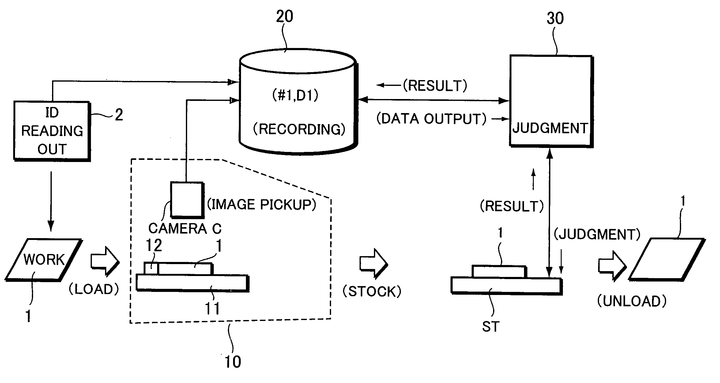
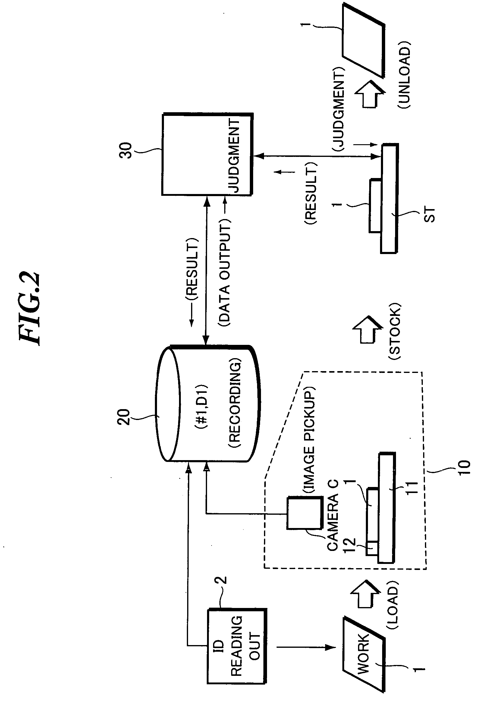
[0020]FIG. 2 is an explanatory conceptual view showing an example of a whole process for carrying out display panel inspection using a display panel inspection apparatus formed according to an embodiment of the present invention. Here, in the present embodiment of the present invention, a display panel (hereinafter, referred to as “work”) to be inspected can be an LCD (Liquid Crystal Display), a PDP (Plasma Display Panel), an organic EL (Electroluminescence) panel and the like.

[0021] An inspection apparatus according to the present embodiment of the present invention comprises: an image measurement unit 10 for lighting a display panel in response to a test signal and pick up the lighted image so as to obtain image measurement data; a data accumulating unit 2...


PUM


Abstract

It is an object of the present invention to provide a display panel inspection apparatus and an inspection method capable of remarkably reducing equipment cost and shortening inspection time. The apparatus comprises: an image measurement unit which lights a display panel (work) in response to a test signal and pick up an image of the lighted display panel, thereby obtaining image measurement data; a data accumulating unit for accumulating the image measurement data of a plurality of display panels as data corresponding to the respective display panels; and a data processing unit which respectively reads out the image measurement data accumulated in the data accumulating unit and performs image processing so as to judge the quality of each display panel. When inspecting a plurality of display panels, the image measurement unit and the data processing unit perform inspections independently. The image measurement unit operates to output identification data for identifying the respective display panels acting as measurement objects and image measurement data to the data accumulating unit, while the data accumulating unit forms a data base for managing the identification data and the image measurement data corresponding to the identification data.

Description

BACKGROUND OF THE INVENTION [0001] The present invention relates to a display panel inspection apparatus and a display panel inspection method. [0002] The present application claims priority from Japanese Application No. 2004-238697, the disclosure of which is incorporated herein by reference. [0003] A display panel such as a plasma display panel, a liquid crystal display panel, and an organic EL (Electroluminescence) panel, upon having been formed as a display panel, is usually subjected to various inspections to check its brightness uniformity with respect to white light emission, its luminescent spot with respect to black color display, its color un-uniformity, its pixel defect and its margin test (an amount of luminescence with respect to an amount of input signal), thereby effecting a quality management on completed products based on the results of such inspections. [0004] A display panel inspection apparatus used at this time, as shown in FIG. 1, has an inspection table J2 on ...

Claims


Application Information

Patent Timeline
IPC IPC(8): G01R31/00
CPCG01N21/95G02F1/1309G01N2021/9513
Inventor KANAI, MIKIO
Owner PIONEER CORP
Why Eureka
Try Eureka