High-resolution and high-power ultrasound method and device, for submarine exploration

a high-power, ultrasound technology, applied in the direction of measuring devices, instruments, scientific instruments, etc., can solve the problems of insufficient fulfilment of all traditional acoustic systems, complicated understanding of the behavior of acoustic waves propagating through sediments, and high-resolution acoustic devices

Inactive Publication Date: 2006-02-23
CONSIGLIO NAT DELLE RICERCHE
View PDF3 Cites 10 Cited by
  • Summary
  • Abstract
  • Description
  • Claims
  • Application Information

AI Technical Summary

Problems solved by technology

It is well known that the behaviour of acoustic waves propagating through sediments is more complicated to understand, and, specifically, the absorption of acoustic energy is higher than in the water column, especially in the frequency band corresponding to higher frequencies.
Traditional acoustic systems seem inadequate to fulfil all possible environmental situations that may be encountered in the exploration of the upper layers of marine sediments, and this is true in particular during prospecting for archaeological research purposes, for which nowadays no high-resolution acoustic devices exist, having an adequate capacity of penetration into the sediments.
Actually, commercially available acoustic systems do not fullfil both of these requirements at the same time, and consequently they cannot be utilised in an ample range of experimental conditions and marine environmental situations.
This makes it impossible to discriminate the pulses reflected by the seabed, ascribable to objects buried in the sediments, from the signals due to cavitation and which appear as noise.
This drawback does not prevent the preceding echographic system from detecting antique cavities formed in the soil, since it suffices in any case—in order to detect said cavities—to receive a signal reflected by the air-soil interface of the cavity, although this signal is disturbed by the cavitation effect (see for instance FIG. 7 of U.S. Pat. No. 4,899,845, of Feb. 13, 1990, issued to the same inventors).
By this array one obtains an improvement of the signal in the time domain, but it shows drawbacks such as a lower acoustic efficiency (defined as the ratio between the emitted acoustic energy and the electrostatic input energy), and a considerably limited frequency band that is insufficient for a high resolution, though the latter is indispensable to detect small findings hidden in the upper layer of the marine sediment; moreover, this apparatus has an excessive cost because it requires a high number of transmission transducers.

Method used


Image

  • High-resolution and high-power ultrasound method and device, for submarine exploration
  • High-resolution and high-power ultrasound method and device, for submarine exploration
  • High-resolution and high-power ultrasound method and device, for submarine exploration

Examples


Embodiment Construction

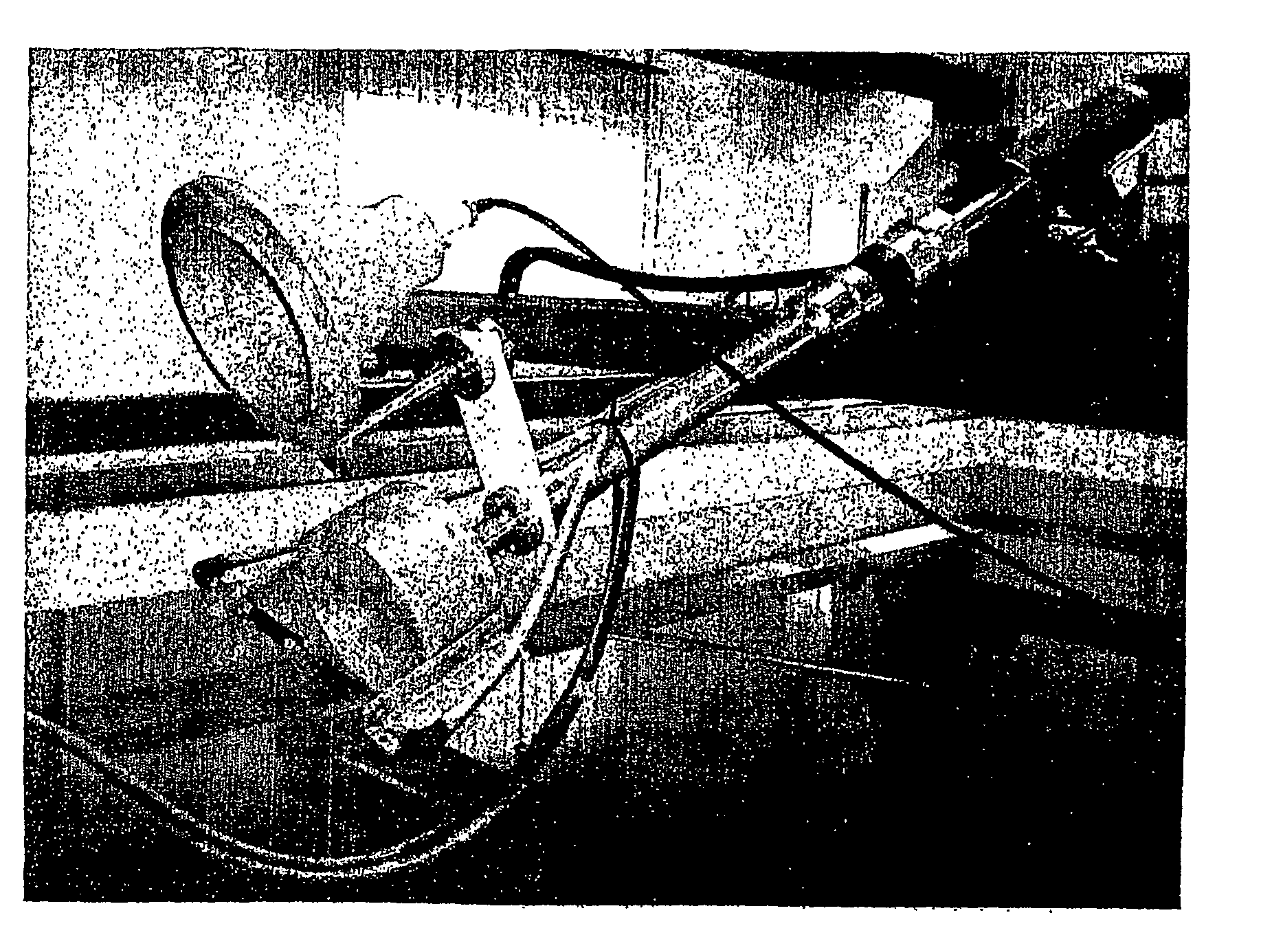
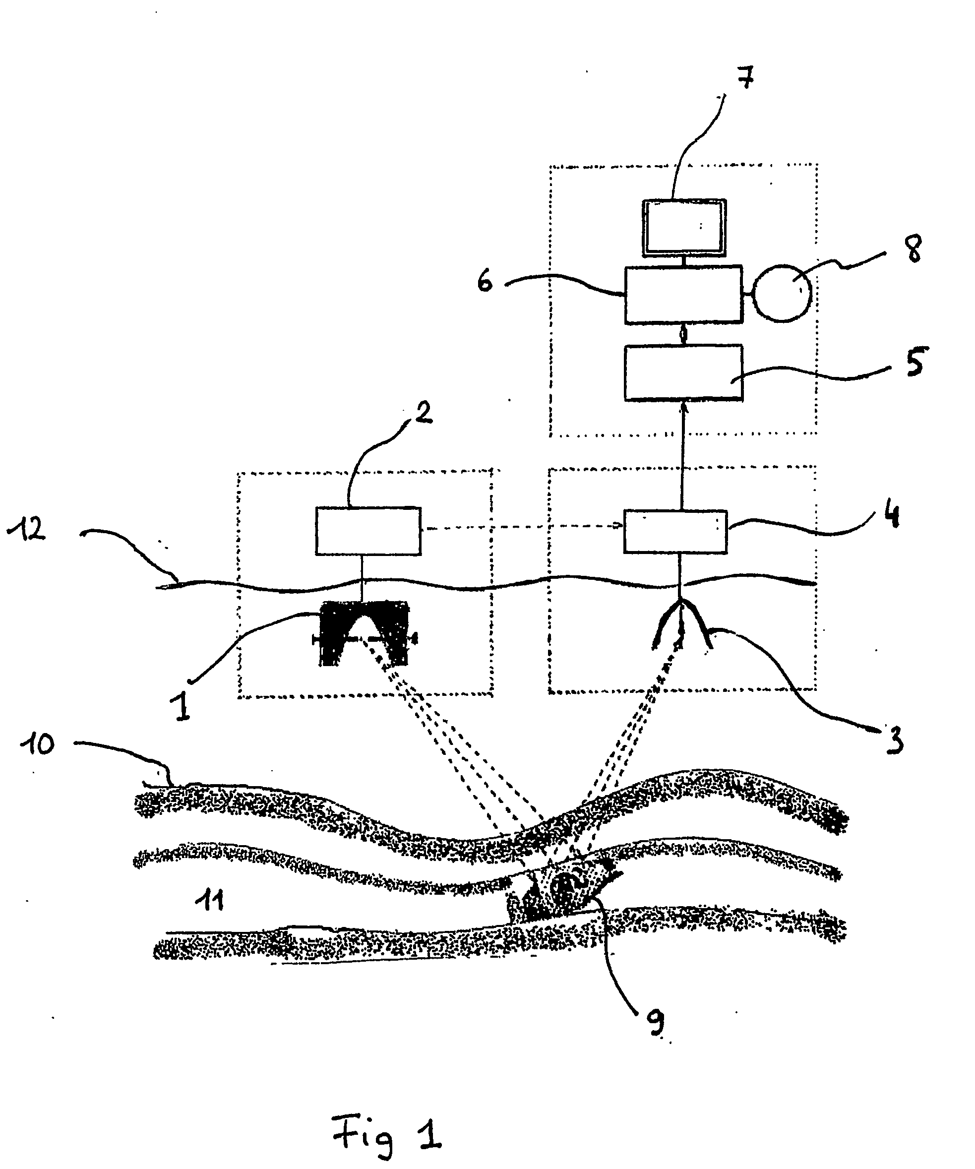
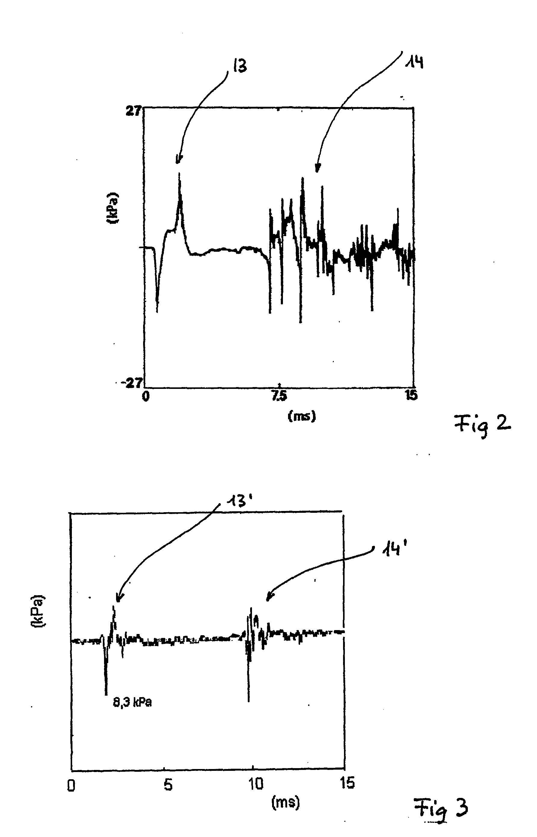
[0028] Before going into the details of the research performed by the inventor, we briefly describe, referring to FIG. 1, the apparatus or device of the present invention. This apparatus includes a parabolic transmitter 1, forming the acoustic source, which is associated to an electronic control unit 2. The transmitter 1 is spaced apart from the receiver 3 by an appropriate distance, which is adjustable according to the prospecting depth. The paraboloidal transmitter 1 is energised by means of a condenser bank (condenser array), not shown in the figures, forming part of the control unit 2. The condenser bank supplies electrostatic energy to the transmitter 1, and the latter converts it into acoustic energy with the aid of the same electronic control unit 2. The receiver, or reception paraboloid 3, is connected to an analog-to-digital converter (ADC) 4 that receives a trigger signal—in the form of an electric signal—from the control unit 2, and transmits the digital data to a micropr...


PUM


Abstract

A method for underwater exploration which makes use of a parabolic transmitter (1) and a parabolic receiver (3), the transmitter (1) and the receiver (3) being both open at their lower side and immersed below the seawater surface. The electric breakdown discharge occurring between both electrodes (15) of the transmitter (1) generates a primary signal and a pulse which is called “cavitation bubble pulse.” The method consists in enhancing the signal (23) produced by the implosion of the cavitation bubble, to the detriment of the primary signal (13″), by appropriately adjusting the value of the “spark gap” (distance d between the electrodes) so as to optimize the delay time (t) and consequently the acoustic efficiency of the transmitter, by transferring the electrostatic energy to the bubble implosion signal.

Description

TECHNICAL FIELD [0001] The present invention generally concerns a high-power and high-resolution ultrasound method used for submarine exploration (survey), and moreover, it relates also to a device for carrying out the same, including a parabolic (that is, paraboloid-like) transmitter of acoustic waves, having a pair of electrodes adequately positioned around its focus, for causing an electric discharge to occur between the electrodes, this discharge being the cause of the generation of the prospecting signal; this device also includes a receiver, having a paraboloid-like configuration as well, and presenting an acoustic pressure sensor localised in its focus, and being appropriately coupled to the transmitter in such a way as to focus the signals that are reflected by objects and by other unhomogeneities buried below the sediments of the seabed. This device or apparatus, is a simplified, but at the same time an innovative and improved version, of an ultrasound ecographic system dev...

Claims


Application Information

Patent Timeline
Patent Type & Authority Applications(United States)
IPC IPC(8): G01V1/157
CPCG01V1/157
Inventor CANNELLI, GIOVANNI BOSCO
Owner CONSIGLIO NAT DELLE RICERCHE
Why Eureka
Try Eureka