
Electronic package for electrical machine

a technology of electrical machines and electronic components, applied in the direction of mechanical energy handling, magnetic circuit rotating parts, magnetic circuit shape/form/construction, etc., can solve the problems of insufficient long-term reliability of the alternator, inability to rapidly dissipate the resulting heat, and difficulty in providing such a bridge rectifier

Inactive Publication Date: 2006-03-02
BORGWARNER INC
View PDF9 Cites 28 Cited by
  • Summary
  • Abstract
  • Description
  • Claims
  • Application Information

AI Technical Summary

Problems solved by technology

However, under certain particularly severe operating conditions, it has become apparent that this cooling of the diodes, and in general terms the cooling of the whole of the current regulating means, can be insufficient to ensure long-term reliability of the alternator.
Bridge rectifiers, as discussed, are typically unable to absorb or conduct these types of excess currents and are also unable to rapidly dissipate the resulting heat.
Due to the space limitations of the alternating current generator, it then becomes very difficult to provide such a bridge rectifier from a feasibility standpoint as well as at an economical cost.
In addition, a six diode configuration does not have the flexibility to adapt to the thermal cooling requirements of a twelve diode rectifier or have brush lengths to match a given application.
The size of the bearing OD and range of temperatures are such that having a direct press-fit between the bearing and SRE frame assembly will result in either having a radial press that is too high, and hence stress at this interface, at one temperature extreme, or a completely loose fit at the other extreme.
Plastic, however, presents its own problems with respect to applied loads, elevated temperature, and time.
Plastic creeps causing problems with radial alignment between the rear bearing and SRE frame assembly.
Plastic also presents a thermal barrier to the outer race of the bearing preventing effective thermal conductance to the aluminum SRE frame assembly.
However, because of the mismatch in thermal expansion between the steel cup and aluminum SRE frame assembly, the steel retaining cup typically includes multiple legs extending radially outward.
Although effective from a product standpoint, such an arrangement is costly.

Method used


Image

  • Electronic package for electrical machine
  • Electronic package for electrical machine
  • Electronic package for electrical machine

Examples


Embodiment Construction

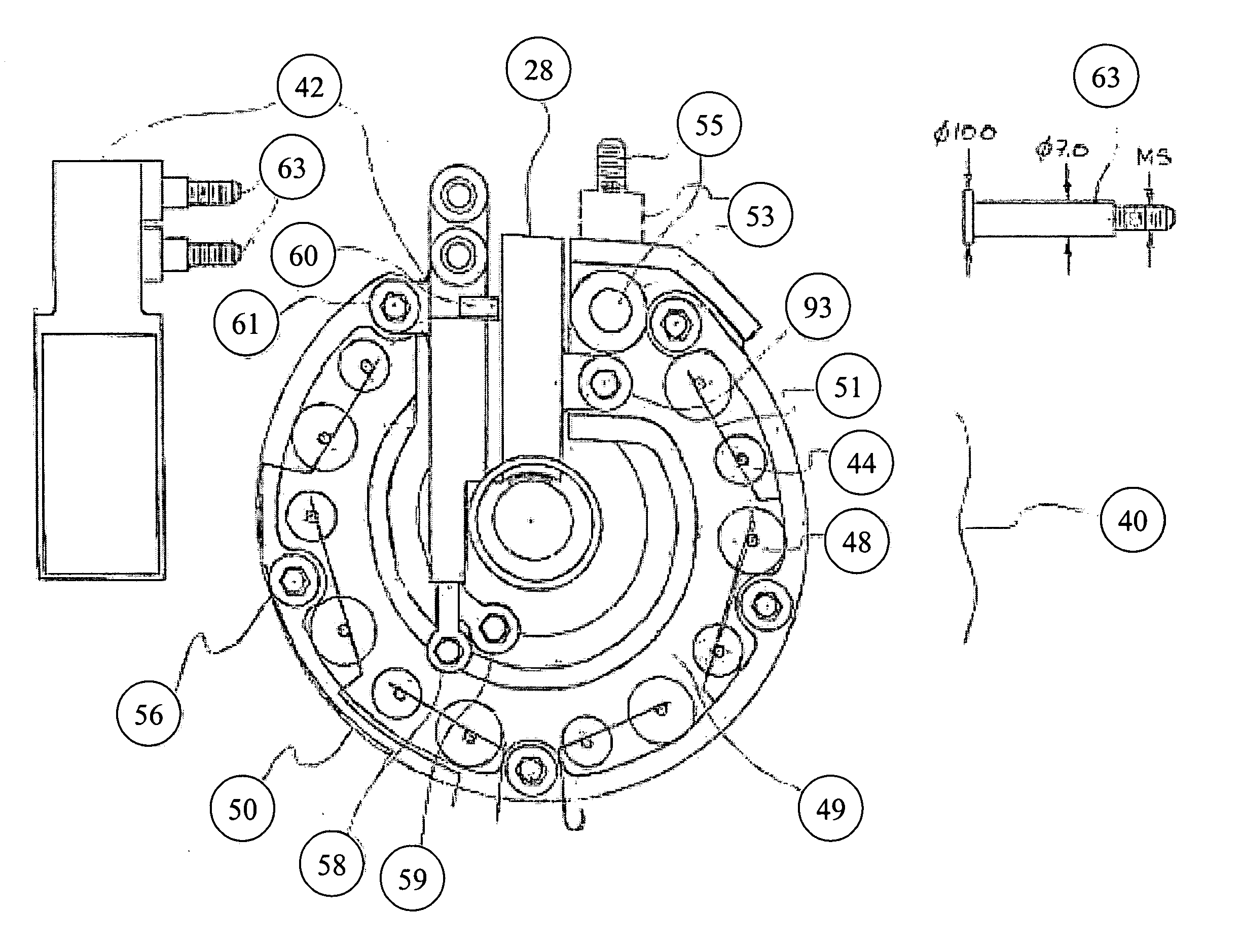
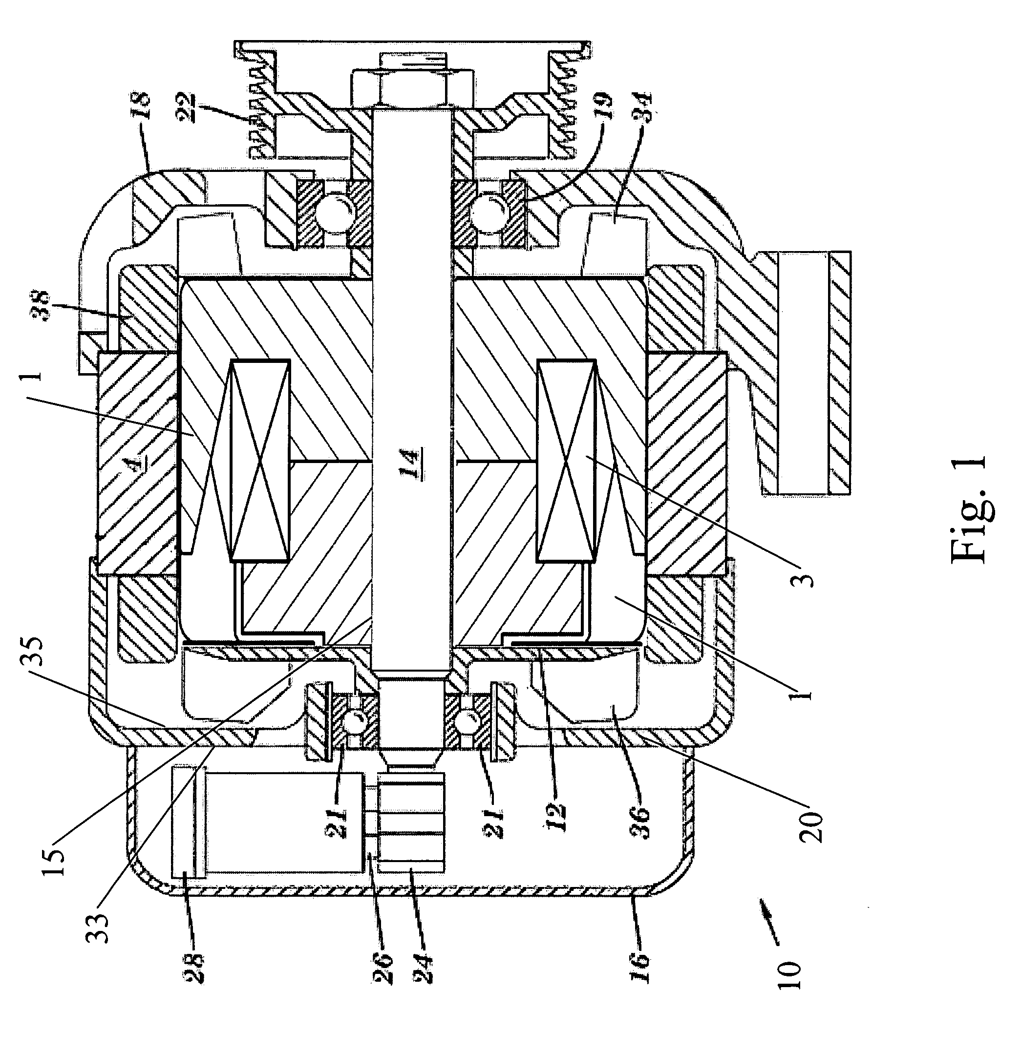
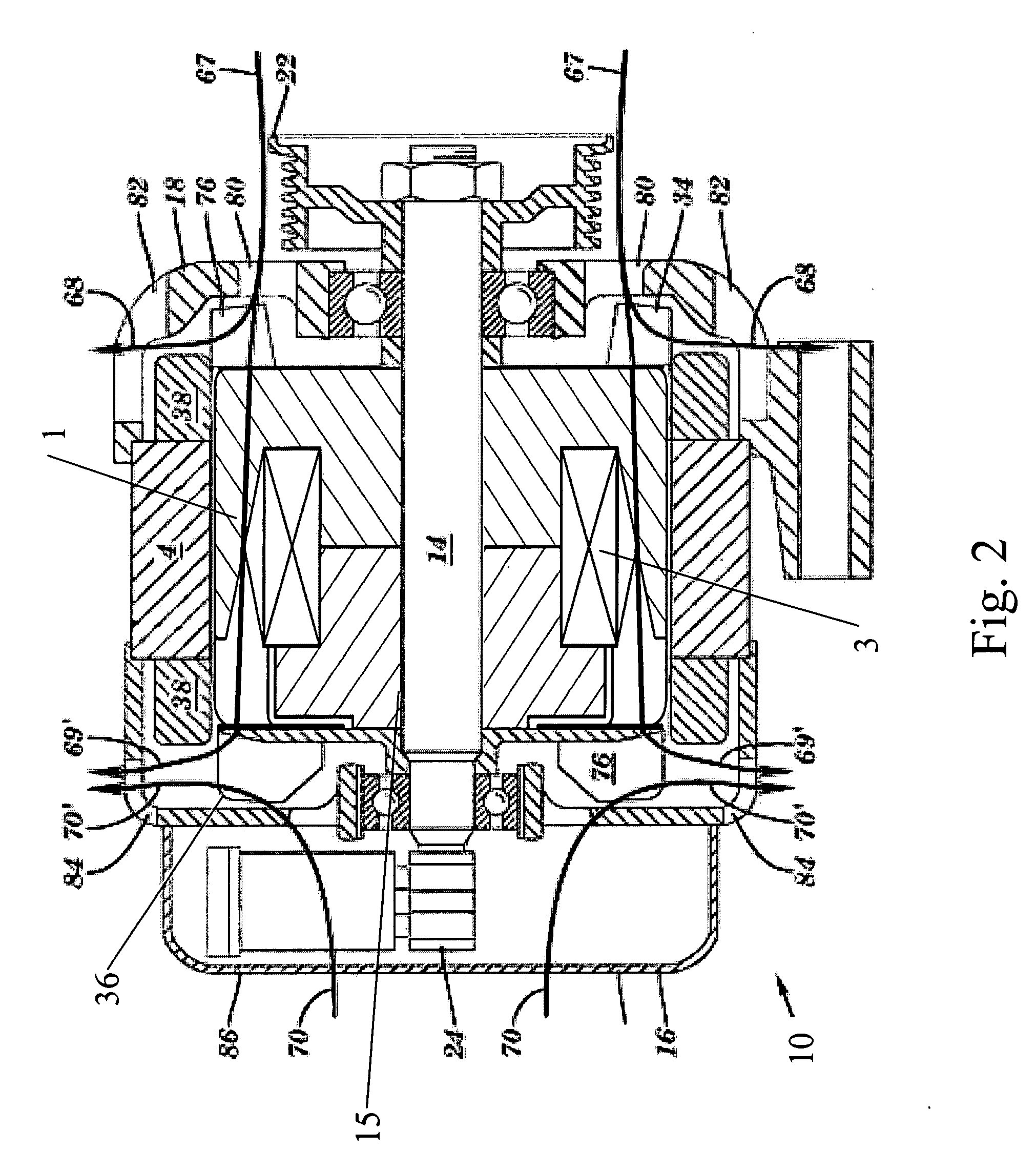
[0038]FIG. 1 illustrates an exemplary rotor assembly 15, containing several components including a shaft 14, a field winding 3 surrounding a core (not shown), and pole segments 1, disposed in an electric machine 10 that operates as an alternator in an exemplary embodiment, and is constructed by rotatably mounting a claw-pole rotor or the rotor assembly 15 by means of the shaft 14 inside a case 16 constituted by a front bracket or drive end frame 18 and a rear bracket or slip ring end (SRE) frame 20, which may be made of aluminum, and fixing a stator 4 to an inner wall surface of the case 16 so as to cover an outer circumferential side of the rotor assembly 15. This type of electric machine is shown in U.S. patent application Ser. No. 10 / 714,147, filed on Nov. 14, 2003, the contents of which are incorporated by reference herein in their entirety.

[0039] The shaft 14 is rotatably supported in the front bracket 18 via a first bearing 19 and the rear bracket 20 via a second bearing 21. ...


PUM


Abstract

Disclosed herein is an electronic package for an electrical machine including a slip ring end frame; a plurality of negative diodes dispersed in an angular fashion in the SRE frame acting as a negative heat sink; a plurality of positive diodes mounted on a separate electrically conductive plate located above a location of the plurality of negative diodes; a non-conductive separator fitted over a series of bosses, configured to electrically insulate; a terminal assembly configured to make appropriate electrical connections between the positive and negative diodes, stator phase leads, and a regulator, which is operably fastened to the SRE frame at a plurality of locations, the regulator electrically connects to the positive heat sink, a stator phase terminal extending from the terminal assembly, SRE frame, and a brush holder; wherein the regulator is perpendicular to the SRE frame.

Description

CROSS REFERENCE TO RELATED APPLICATION [0001] This application claims the benefit of U.S. Provisional Application No. 60 / 606,348 filed Sep. 1, 2004 the contents of which are incorporated by reference herein in their entirety.TECHNICAL FIELD [0002] This application relates generally to an electrical apparatus. More specifically, this application relates to an electronic component package having a diode rectifier bridge, regulator, and brush holder assembly for a compact electrical machine having improved cooling characteristics. BACKGROUND [0003] Electrical loads for vehicles continue to escalate. At the same time, the overall package size available for the electrical generator continues to shrink. Consequently there is a need for a higher power density system and method of generating on-board electricity. [0004] The increase in the demand for current to be produced by an alternator leads to a need for corresponding adaptation of the system for current regulation, and particularly of...

Claims


Application Information

Patent Timeline
IPC IPC(8): H02K9/00H02K11/04H02K11/00H02K19/36
CPCH02K5/1732H02K5/20H02K19/365H02K11/0073H02K11/046H02K9/06H02K11/33H02K5/207H02K11/05
Inventor BRADFIELD, MICHAEL D.
Owner BORGWARNER INC
Features
  • Generate Ideas
  • Intellectual Property
  • Life Sciences
  • Materials
  • Tech Scout
  • Unparalleled Data Quality
  • Higher Quality Content
  • 60% Fewer Hallucinations
Learn More