System and method for reducing latency in display of computer-generated graphics

a technology of computer graphics and latency reduction, applied in the field of display, can solve the problems of increasing display circuitry complexity, improving system presentation, and relatively expensive graphics adapters and monitors, and achieve the effect of reducing display latency, responding more quickly and naturally

Inactive Publication Date: 2006-03-02
MICROSOFT TECH LICENSING LLC
View PDF4 Cites 27 Cited by
  • Summary
  • Abstract
  • Description
  • Claims
  • Application Information

AI Technical Summary

Benefits of technology

[0013] The source preferably includes a video graphics array (VGA) adapter. Also, the display comprises a projector, which may be included in an interactive display system, wherein a user interacts w

Problems solved by technology

However, the improved systems did present some disadvantages.
Not surprisingly, high quality graphics adapters and monitors were relatively expensive.
However, the improved display capabilities of display monitors adds complexity to the display circuitry.
Circuitry required to adjust the displayed image adds cost to the display.
Moreover, the additional processing involved in, for example, rescaling the image, delays the image generation process.
Although in many applications, a slight image generation delay does not pose a problem, in computer games, latency will likely pose a concern, because it detracts from the enjoyment and naturalness of the machine-human interaction.
The latency of a system in responding to user input on the display can cause the human interaction in a virtual environment or electronic game to appear disconnected, if the delay between a user input and its effect on the virtual environment is sufficiently long to b

Method used


Image

  • System and method for reducing latency in display of computer-generated graphics
  • System and method for reducing latency in display of computer-generated graphics
  • System and method for reducing latency in display of computer-generated graphics

Examples


Embodiment Construction

Exemplary Computing System for Implementing Present Invention

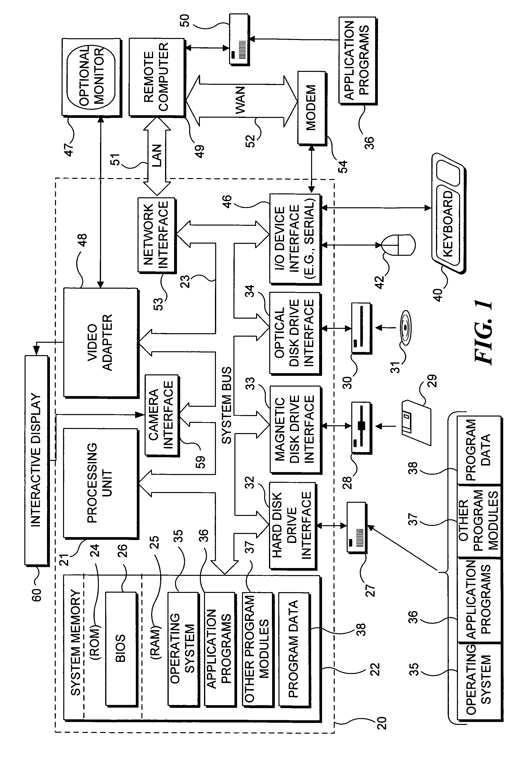
[0023] With reference to FIG. 1, an exemplary system suitable for implementing various portions of the present invention is shown. The system includes a general purpose computing device in the form of a conventional PC 20, provided with a processing unit 21, a system memory 22, and a system bus 23. The system bus couples various system components including the system memory to processing unit 21 and may be any of several types of bus structures, including a memory bus or memory controller, a peripheral bus, and a local bus using any of a variety of bus architectures. The system memory includes read only memory (ROM) 24 and random access memory (RAM) 25. A basic input / output system 26 (BIOS), containing the basic routines that help to transfer information between elements within the PC 20, such as during start up, is stored in ROM 24. PC 20 further includes a hard disk drive 27 for reading from and writing to a hard disk ...


PUM


Abstract

An interactive display system wherein a projector receives signals from a graphics source in a manner that reduces latency in images projected onto a display surface. The signals include a pixel clock signal, pixel attribute signals, and synchronization signals. The pixel clock signal is used to clock sample and hold registers at the projector to preserve the pixel attribute signals received from the graphics source. The preserved pixel attribute signals, along with position signals corresponding to the synchronization signals, are presented directly to the projector. Parameters of the projector are known, and all gain, gamma correction, and scaling are performed before the signals are provided by the graphics source. Thus, it is unnecessary to digitize, store, adjust, or otherwise process pixel attribute signals at the projector, which simplifies processing of the graphics signals and reduces latency in generating the image in response to an input on the display surface.

Description

FIELD OF THE INVENTION [0001] The present invention generally pertains to displays, and more specifically, to controlling latency in the presentation of computer graphics in response to graphic display signals generated by a computing system. BACKGROUND OF THE INVENTION [0002] Today's computer display systems are capable of generating very high quality images. By contrast, in the early 1980s, the color displays commonly available with computers offered only 320 by 200 pixel resolution, with a maximum of four colors. During the 1980s, however, increasingly better computer graphics systems became available that offered higher resolution and a much larger number of colors. However, the improved systems did present some disadvantages. Not surprisingly, high quality graphics adapters and monitors were relatively expensive. Further, early high resolution monitors were capable of working only with one type of graphics adapter. [0003] The advent of multi-scanning monitors relieved part of t...

Claims


Application Information

Patent Timeline
IPC IPC(8): G09G5/00
CPCG09G5/006H04N5/74G09G2370/04G09G5/363
Inventor YEE, DAWSON L.
Owner MICROSOFT TECH LICENSING LLC
Why Eureka
Try Eureka