Optical access network of wavelength division method and passive optical network using the same

a wavelength division and optical access network technology, applied in the field of optical access networks, can solve the problems of large initial investment costs for the above-described optical access network, serious loss can occur when limiting bandwidth, network requires a large amount of initial costs and costs associated with the maintenance of the network including optical fibers, and achieve the effect of lowering investment costs

Inactive Publication Date: 2006-03-02
SAMSUNG ELECTRONICS CO LTD
View PDF13 Cites 115 Cited by
  • Summary
  • Abstract
  • Description
  • Claims
  • Application Information

AI Technical Summary

Benefits of technology

[0021] Accordingly, the present invention has been made to solve the above-mentioned problems occurring in the prior art and provides additional advantages, by providing a wavelength division multiplexed optical access network capable of offering broadband services to subscribers of wire and wireless networks at a ultra high speed while lowering the investment costs required for constructing the WDM optical access network.

Problems solved by technology

However, large initial investment costs are required for the above-described optical access network.
In a wireless network, although mobility and point to multi-point connection can be provided, serious loss can occur when limiting bandwidths.
However, since the conventional WDM optical access network provides services mainly for wire network subscribers, the network requires a large amount of initial costs and costs associated with the maintenance of the network including laying of optical fibers.
Similarly, the cost of implementing the radio-over-fiber network is also high.
Therefore, the scalability and usage of the radio-over fiber network is restricted
However, the drawbacks of radio-over-fiber network, which requires a large amount of initial investment including optical fiber laying costs and time r to construct a dedicated radio-over-fiber network, has prevented the availability of such network.

Method used


Image

  • Optical access network of wavelength division method and passive optical network using the same
  • Optical access network of wavelength division method and passive optical network using the same
  • Optical access network of wavelength division method and passive optical network using the same

Examples


first embodiment

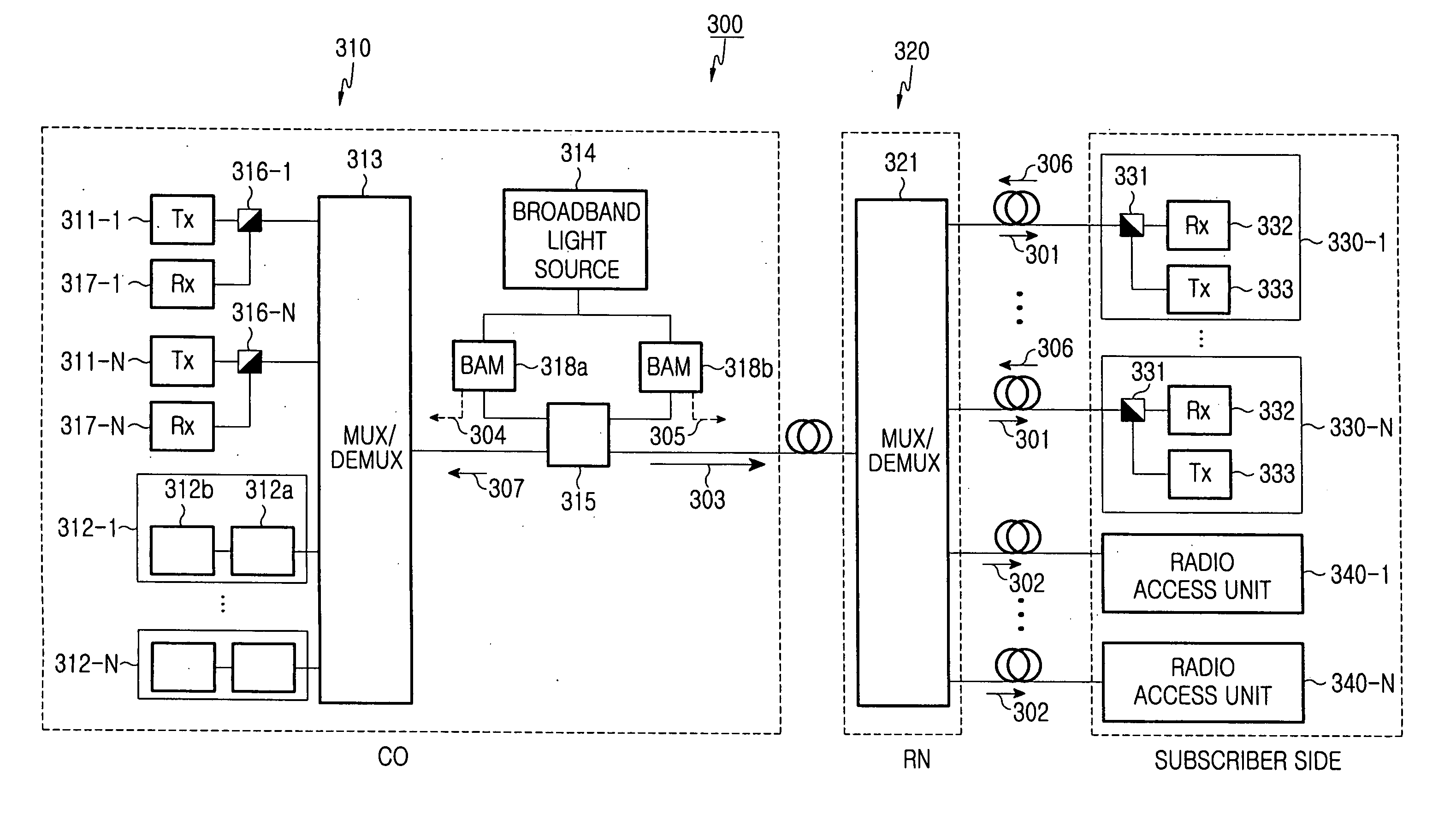
[0038]FIG. 3 illustrates the structure of an optical access network according to the present invention. FIGS. 4A to 4D are graphical illustration of the optical access network shown in FIG. 3.

[0039] Referring to FIG. 3, a wavelength division multiplexed (WDM) optical access network 200 according to the first embodiment of the present invention includes a central office (CO) 210 for multiplexing first optical signals 203 used for providing a wire data service at a high speed and second optical signals 204 applied in order to transmit a wireless data service to subscriber terminals, a remote node (RN) 220 for de-multiplexing a multiplexed optical signal 202 received from the CO 210, and a subscriber side 230 for receiving the first optical signals 203 and the second optical signals 204 de-multiplexed in the RN 220. The subscriber side 230 includes a plurality of subscribers 231-1 to 213-N, each of which is connected to the RN 220, and a plurality of radio access units, each of which i...

third embodiment

[0066]FIG. 10 is a block diagram illustrating the structure of a bi-directional passive optical network according to the present invention, and FIG. 11 is a graph illustrating a signal flow in each component shown in FIG. 10.

[0067] Referring to FIG. 10, a passive optical access network 400 according to the third embodiment of the present invention includes a central office (CO) 410 for multiplexing first downstream optical signals data1 and data2 used for wire data transmission at a high speed and second downstream optical signals used for providing a wireless data service, a remote node (RN) 420 linked to the CO 410, a plurality of subscribers 430 linked to the RN 420, and a plurality of radio access units linked with the RN 420.

[0068] The CO 410 multiplexes the first downstream optical signals and the second downstream optical signals into downstream optical signals to be output to the RN 420 and de-multiplexes upstream optical signals multiplexed in the RN 420 to first upstream ...


PUM


Abstract

A wavelength division multiplexed optical access network including a central office for multiplexing first optical signals used for transmitting a high-speed wire data service to a subscriber side and second optical signals used for transmitting a wireless data service to a remote subscriber terminal, a remote node connected to the central office through an optical fiber and for de-multiplexing a multiplexed optical signal received from the central office, a plurality of subscribers connected to the remote node, each subscriber receiving a first optical signal having a corresponding wavelength from among the de-multiplexed first optical signals, and a plurality of radio access units connected to the remote node, each radio access unit converting a second optical signal having a corresponding wavelength from among the de-multiplexed second optical signals into a wireless electric signal and wirelessly transmitting the wireless electric signal.

Description

CLAIM OF PRIORITY [0001] This application claims priority to an application entitled “Optical Access Network of Wavelength Division Method And Passive Optical Network Using The same,” filed in the Korean Intellectual Property Office on Aug. 28, 2004 and Jul. 8, 2005 and assigned Serial Nos. 2004-68215 and 2005-61585, respectively, the contents of which are incorporated herein by reference. BACKGROUND OF THE INVENTION [0002] 1. Field of the Invention [0003] The present invention relates to an optical access network, and more particularly to a wavelength division multiplexed optical access network capable of servicing both a wire network and a wireless network. [0004] 2. Description of the Related Art [0005] As a demand for more data capability in a wire communication system or a mobile communication system increases, it is necessary for access networks to process data having wider band widths in order to provide various high-capacity multimedia data such as images, moving pictures, a...

Claims


Application Information

Patent Timeline
Patent Type & Authority Applications(United States)
IPC IPC(8): H04J14/00H04B10/27H04B10/272H04J14/02
CPCH04B10/25752H04B10/25753H04J14/02H04J14/0226H04J14/025H04J14/0282H04J14/0298H04J14/0246H04J14/0227
Inventor LEE, GYU-WOONGHWANG, SEONG-TAEKLEE, JAE-HOONSHIM, CHANG-SUPOH, YUN-JEKIM, YONG-GYOOJUNG, DAE-KWANG
Owner SAMSUNG ELECTRONICS CO LTD
Why Eureka
Try Eureka