Optical switch
a technology of optical switch and optical pulse, which is applied in the field of optical switch, can solve the problems of waveform distortion increase in propagation loss, and reduction of signal to noise ratio (s/n) of optical pulse signal, and achieve the effect of stable switching operation
- Summary
- Abstract
- Description
- Claims
- Application Information
AI Technical Summary
Benefits of technology
Problems solved by technology
Method used
Image
Examples
first embodiment
[0056] (Structure)
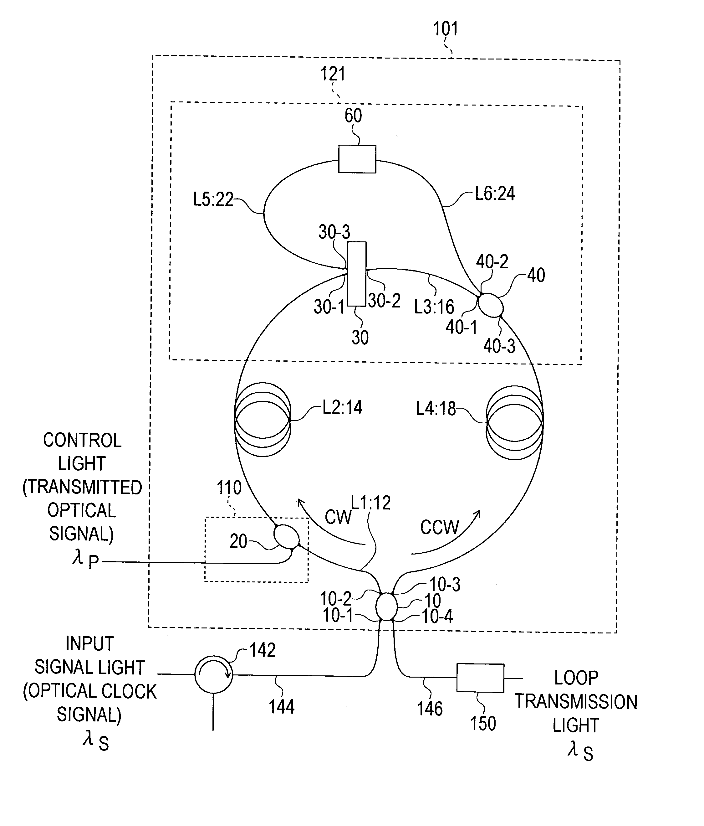
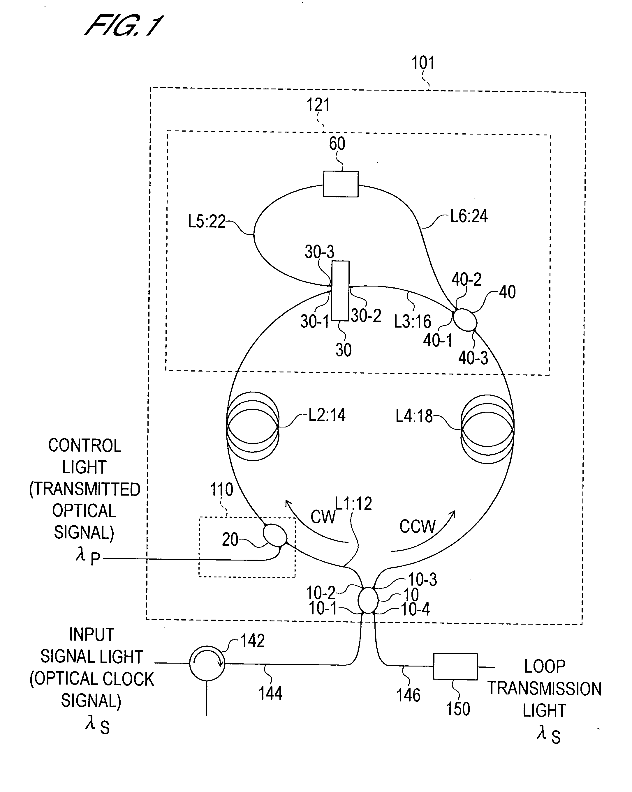
[0057] The structure of a first optical switch serving as a first embodiment of the present invention will now be described with reference to FIG. 1. The first optical switch is constituted by a loop-form optical waveguide loop circuit 101 formed from an optical nonlinear medium, and control light input means 20 of phase control means 110 for inputting a control light into the optical waveguide loop circuit 101, and also comprises a wavelength demultiplexing / multiplexing circuit 121.
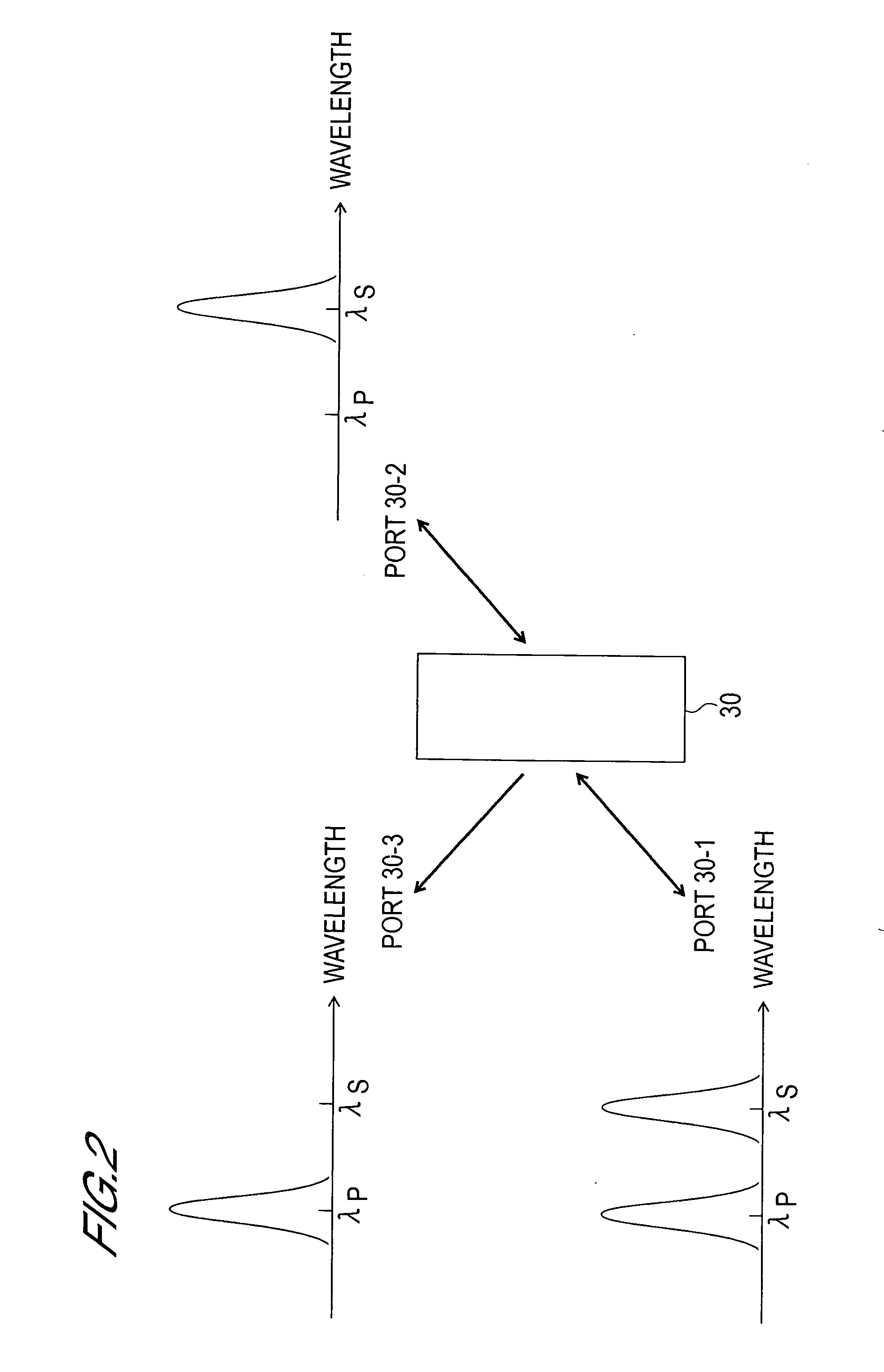
[0058] The optical waveguide loop circuit 101 is constituted by an optical path (also referred to as “path L1” hereafter) formed from a first optical fiber 12 extending from an optical demultiplexer / multiplexer 10 to the control light input means 20, an optical path (also referred to as “path L2” hereafter) formed from a second optical fiber 14 extending from the control light input means 20 to the wavelength demultiplexing / multiplexing circuit 121, and an optical path (also referred ...
second embodiment
[0117] (Structure)
[0118] The structure of a second optical switch serving as a second embodiment of the present invention will now be described with reference to FIG. 4. The second optical switch is constituted by a loop-form optical waveguide loop circuit 102 formed from an optical nonlinear medium, and the control light input means 20 of the phase control means 110 for inputting a control light into the optical waveguide loop circuit 102, and also comprises a wavelength demultiplexing / multiplexing circuit 122.
[0119] The constitution of the second optical switch differs from the constitution of the first optical switch described above in the following manner. Firstly, the optical fiber constituting the paths L1 through L6 is polarization-maintaining single-mode fiber. In other words, the paths L1 through L6 are constituted by first through sixth polarization-maintaining single-mode fibers 13, 15, 17, 19, 23, and 25 respectively. Further, the optical demultiplexer / multiplexer 10, ...
third embodiment
[0154] (Structure)
[0155] The structure of a third optical switch serving as a third embodiment of the present invention will now be described with reference to FIG. 6. The third optical switch is constituted by a loop-form optical waveguide loop circuit 103 formed from an optical nonlinear medium, and the control light input means 20 of the phase control means 110 for inputting a control light into the optical waveguide loop circuit 103, and also comprises a wavelength demultiplexing / multiplexing circuit 123.
[0156] In the third optical switch, the optical waveguide loop circuit 103 is constituted by an optical path (also referred to as “path L1” hereafter) formed from the first polarization-maintaining single-mode fiber 13 extending from the optical demultiplexer / multiplexer 10 to the control light input means 20, an optical path (also referred to as “path L2” hereafter) formed from a second polarization-maintaining single-mode fiber 51 extending from the control light input means...
PUM
| Property | Measurement | Unit |
|---|---|---|
| angle | aaaaa | aaaaa |
| angle | aaaaa | aaaaa |
| length | aaaaa | aaaaa |
Abstract
Description
Claims
Application Information
 - R&D
- Intellectual Property
- Life Sciences
- Materials
- Tech Scout
- Unparalleled Data Quality
- Higher Quality Content
- 60% Fewer Hallucinations
Browse by: Latest US Patents, China's latest patents, Technical Efficacy Thesaurus, Application Domain, Technology Topic, Popular Technical Reports.
© 2025 PatSnap. All rights reserved.Legal|Privacy policy|Modern Slavery Act Transparency Statement|Sitemap|About US| Contact US: help@patsnap.com


