Device, system and method for improving efficiency and preventing degradation of energy storage devices

a technology of energy storage device and efficiency improvement, which is applied in the direction of secondary cell maintenance/maintenance, cell components, maintenance/maintenance of primary cells, etc., can solve the problems of increasing the amount of time and current required to break these bonds, deteriorating the battery's capacity, and affecting the load carrying ability of the battery, so as to prevent degradation of a chemical-to-electrical and improve energy performance , the effect of maintaining ionic bonding

Active Publication Date: 2006-03-09
ULTRASONIC ENERGY EFFICIENCY SOLUTIONS
View PDF24 Cites 26 Cited by
  • Summary
  • Abstract
  • Description
  • Claims
  • Application Information

AI Technical Summary

Benefits of technology

[0033] Disclosed herein is a method and related device for improving energy performance and substantially preventing degradation of a chemical-to-electrical energy conversion process of an energy storage device, comprising the steps of mechanically exciting chemical reaction products within the energy storage device at energy levels proximate which covalent bonds with a matrix of the energy storage device would form absent excitation, thereby substantially maintaining ionic bonding between the chemical reaction products and the matrix and substantially preventing the chemical reaction products from covalently bonding with the matrix; and introducing the mechanical excitations into the energy storage device via an active material mechanically-responsive to electromagnetic signals, in response to an electromagnetic signal; whereby: degradation is substantially prevented by substantially preventing the covalent bonds from forming and by exciting the energy storage device mechanically rather than via degrading electrical exci

Problems solved by technology

Without these pores the battery's load carrying ability would suffer greatly.
It is the formation of PbSO4's within the matrix that deteriorates the battery's capacity over time.
At this point the amount of time and current required to break these bonds will have to be increased, and the collateral damage to the battery resulting from such removal increases significantly.
Sulfation lowers the current-carrying capacity and over time limits the energy storage capacity of the battery.
It also diminishes the life of the battery and can cause structural damage.
It is this limitation that requires users to apply voltages much higher than that of the battery itself in order to recharge it, and that results in batteries being made larger then they would otherwise need to be to store and deliver a given quantity of energy.
Early attempts to eliminate lead-acid sulfation began with equalization or “over charging.” This process was successful at removing most of the deposits, but at a very high cost to the battery life span, due to the erosion of the positive plate grid structure.
The process, being highly exothermic, results in heat generation, plate warpage and mechanical stress on cell components.
This improved technique is still unable to remove the oldest and most stable sulfate deposits from the plates.
Thus, this process also results in the adverse factors mentioned above, and wastes energy.
In addition, this process of charging is very time-consuming.
However, they still rely on pulsed electrical stimulation of the battery, which itself wastes energy and damages the battery.
A sharp electrical pulse at such high frequency to remove sulfate deposits which have already formed is akin to attacking the matrix with a jackhammer: the deposits may be removed, but

Method used


Image

  • Device, system and method for improving efficiency and preventing degradation of energy storage devices
  • Device, system and method for improving efficiency and preventing degradation of energy storage devices
  • Device, system and method for improving efficiency and preventing degradation of energy storage devices

Examples


Embodiment Construction

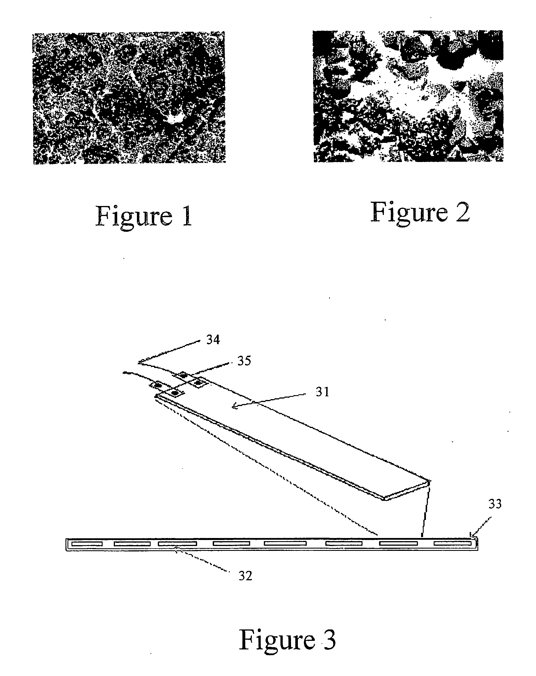
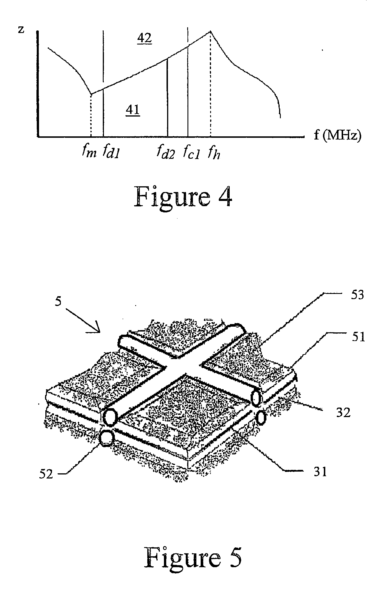
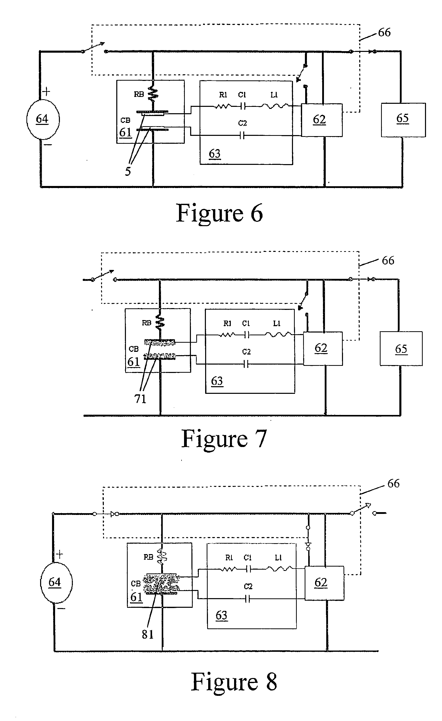
[0046] This disclosure will demonstrate a method and / or a process that can be used within an energy storage device 10 (e.g., battery, or any other energy storage device 10 using a matrix 51 with an electrolyte) to prevent sulfate deposits or their counterparts from reaching a level that will degrade the device. In doing so, several benefits will become apparent.

[0047] However, this disclosure is not limited to energy storage devices. The disclosures herein will work to assist several types of reversible chemical reactions. A solar cell can benefit by better preparing the cell to transfer energy. And, in general, this disclosure can be used to help with any chemical reaction for which its constituents “plate out” thus impeding the reverse reaction. It is also the purpose of this disclosure to demonstrate, by applying this process to a technology already in place, the present limitations that will be eliminated. Energy storage devices, such as the lead-acid batteries used for illustr...


PUM


Abstract

Disclosed herein is a method and related device for improving energy performance and substantially preventing degradation of a chemical-to-electrical energy conversion process of an energy storage device (10), comprising the steps of: mechanically exciting chemical reaction products within the energy storage device (10) at energy levels proximate which covalent bonds with a matrix (51) of the energy storage device (10) would form absent excitation, thereby substantially maintaining ionic bonding between the chemical reaction products and the matrix (51) and substantially preventing the chemical reaction products from covalently bonding with the matrix (51); and introducing the mechanical excitations into the energy storage device (10) via an active material (31) mechanically-responsive to electromagnetic signals, in response to an electromagnetic signal.

Description

FIELD OF THE INVENTION [0001] This invention pertains generally to improving the electrical performance of energy storage devices, and in particular to improving the efficiency and preventing electrode degradation of an energy storage device. BACKGROUND OF THE INVENTION [0002] The lead (Pb) and lead dioxide (PbO2) material used for lead-acid battery electrodes (hereinafter the “matrix”) are very porous materials. This porosity allows the electrolyte completely to penetrate the matrix and chemically react within it. This in turn increases the current-carrying capacity of the battery. Without these pores the battery's load carrying ability would suffer greatly. Unfortunately, nothing is gained without giving something up. FIG. 1 illustrates a “like-new, porous electrode” which has not been in contact with electrolyte. FIG. 2 illustrates a similar electrode after six months of use. While lead-acid batteries will be used here for illustrative purposes, analogous considerations apply gen...

Claims


Application Information

Patent Timeline
IPC IPC(8): H01M2/12H01MH01M2/38H01M10/42H01M10/44
CPCH01M4/12Y02E60/126H01M4/23H01M4/24H01M4/56H01M4/5825H01M10/0525H01M10/06H01M10/12H01M10/345H01M10/42H01M10/4214H01M10/4235H01M10/44Y02E60/122Y02E60/124H01M4/13Y02E60/10
Inventor KELLY, SHAWNPGALGANA, JOSEPHR
Owner ULTRASONIC ENERGY EFFICIENCY SOLUTIONS
Why Eureka
Try Eureka