Liquid delivery device

a liquid delivery and liquid technology, applied in the field of liquid delivery devices, can solve the problems of inability to use the above process, inability to retain the original composition of the sample during the delivery, and inability to achieve electrophoretic separation, so as to improve the reliability of analysis, reduce the dead volume, and reduce the delivery time

Inactive Publication Date: 2006-03-16
CANON KK +1
View PDF40 Cites 20 Cited by
  • Summary
  • Abstract
  • Description
  • Claims
  • Application Information

AI Technical Summary

Benefits of technology

[0013] The present invention intends also to provide a fluid delivery device comprising a passive valve having a simple structure and serving also as a flowsensor.
[0017] A method for introducing a sample into an analyzing device connected with the outside of the liquid delivery device mainly is explained in the following. A usage of the present invention with the method has an advantage in that a plurality of analyzing devices can be used by replacing the connected analyzing device with another analyzing device to be connected. The present invention is, however, limited to this usage. Alternatively, both a region on which the liquid delivery device of the present invention is located and a region having the analyzing function may be formed on a common TAS chip. This embodiment can reduce the delivery time since the analyzing region is formed in the vicinity of the delivery device. In addition, any connecting portion is unnecessary for the embodiment so that the sample plug hardly loses the shape, to improve the reliability of analysis. Further, the dead volume can be decreased, which enables small amounts of the buffer solution and the mobile phase.
[0018] The fluid delivery device of the present invention can serve also as a switch or a flowsensor, realizing a microchannel system for delivery of a fluid by controlling the flow rate with a simple structure of the device. In particular, the fluid delivery device of the present invention is useful in a miniature fuel cell which requires a simple structure of the cell and precise control of the fuel feed.

Problems solved by technology

Conversely, however, the immediate beginning of the component separation after sample plug formation makes it impossible to retain the original composition of the sample during the delivery.
Therefore, the above process cannot be utilized in the case where the electrophoretic separation is undesirable, for instance, in the case where a certain amount of the sample is delivered to outside analysis apparatus.
Further, the electroosmosis generates a low driving pressure, being not suitable for introduction of the sample to an analysis apparatus having a high flow resistance such as an HPLC column.
However, known microvalves require an external power source such as a piezoelectric element, electrostatic driving means, and a pressure source, and complicated structure of the device.
Therefore, a sophisticated system such as the one for delivering a certain amount of a sample cannot be constituted by using conventional passive valves only.
The conventional flowsensor and the active-driven microvalve are complicated in the structure, so that the provision of both the flowsensor and the microvalve will make larger the entire system disadvantageously.

Method used


Image

  • Liquid delivery device
  • Liquid delivery device
  • Liquid delivery device

Examples


example 1

[0117] In this Example, a liquid delivery device is practically produced which has valves controlled by pressure change of the fluid.

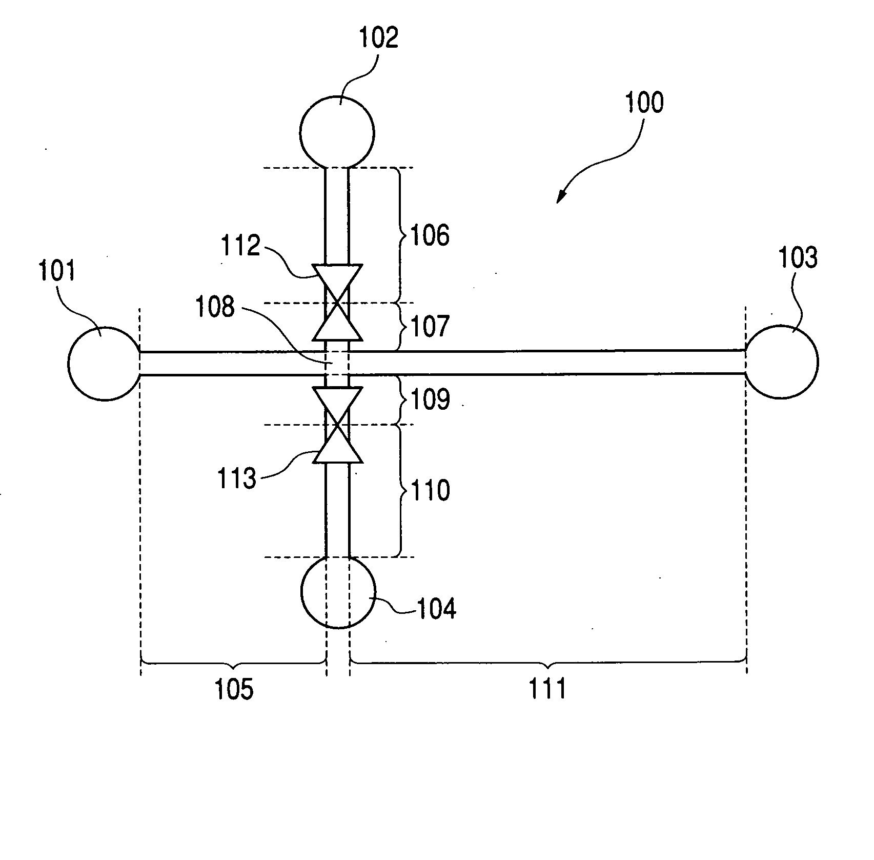
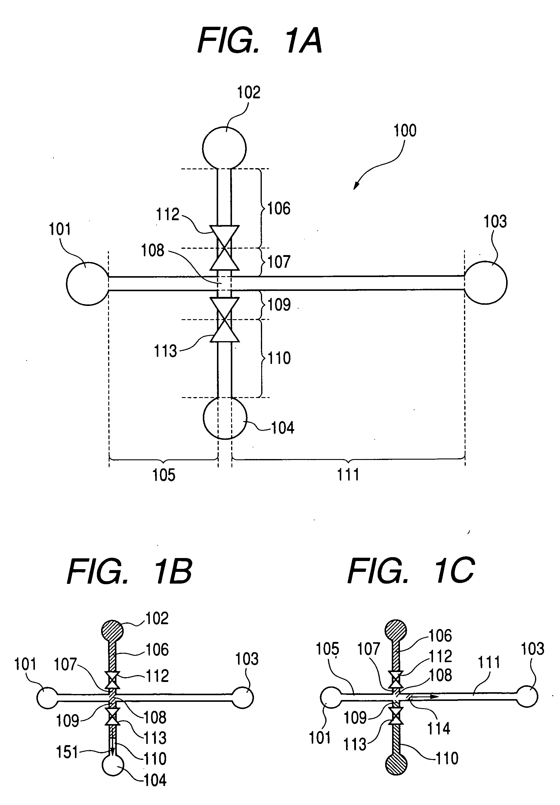
[0118]FIGS. 5A, 5B, and 5C show a specific example of production of the fluid delivery device shown in FIGS. 1A, 1B, and 1C. The fluid delivery device is constituted of substrates 500, 501, 502, 503, and 504 as shown in FIG. 5B. FIG. 5A is a plan view of substrate 500 in which channels shown in FIGS. 1A to 1C are formed. FIG. 5B is a sectional view taken along line 5B-5B in FIG. 5A. FIG. 5C is a plan view taken along line 5C-5C in FIG. 5A.

[0119]FIG. 5B shows specifically the route of fluid flow from flow channel 109 through the valve and flow channel 110 to reservoir 104. The fluid having passed through flow channel 109 in substrate 500 is injected via through-hole 505 in substrate 504 into large channel region 304 in substrate 503. Flat plate 301 provided in substrate 503 is displaced depending on the fluid pressure and the spring constant of spring...

example 2

[0132] With the device prepared above as shown in FIGS. 5A, 5B, and 5C, a unit for separation and analysis is constructed for analysis of a mixture solution containing benzoic acid, salicylic acid, and phenol by HPLC (high performance liquid chromatography). FIGS. 7A and 7B illustrate the unit schematically.

[0133] Unit 700 is constructed on a substrate, having first channel 710, second channel 703-704, third channel 711, fourth channel 706-707, injecting intersection 705, valve 708 in channel 703-704, and valve 709 in channel 706-707. Reservoir 701 is connected to the end of flow channel 703 at the side opposite to valve 708, and reservoir 702 is connected to the end of flow channel 707 at the side opposite to valve 709. Flow channel 710 is connected to pump 712 and flow controller 713 at the outside of unit 700 at the channel end opposite to intersection 705 for injection. Flow channel 711 is connected to an outside analysis apparatus, HPLC column 714, at the channel end opposite ...

example 3

[0140] With the device for analysis of FIGS. 5A, 5B, and 5C, an HPLC apparatus is constructed for separation and analysis of five kinds of proteins in a solution including glutamate dehydrogenase, lactate dehydrogenase, enolase, adenylate kinase, and cytochrome c. FIGS. 7A and 7B show the device schematically.

[0141] Unit 700 is constructed on a substrate, having first channel 710, second channel 703-704, third channel 711, fourth channel 706-707, injecting intersection 705, valve 708 in channel 703-704, valve 709 in channel 706-707. Reservoir 701 is connected to the end of flow channel 703 at the side opposite to valve 708, and reservoir 702 is connected to the end of flow channel 707 at the side opposite to valve 709. Flow channel 710 is connected to pump 712 and flow controller 713 at the outside of unit 700 at the channel end opposite to intersection 705 for injection. Flow channel 711 is connected to an outside analysis apparatus, HPLC column 714, at the channel end opposite to...


PUM

PropertyMeasurementUnit
sizeaaaaaaaaaa
thicknessaaaaaaaaaa
pressureaaaaaaaaaa

Abstract

A fluid delivery device is provided which comprises a microchannel device for cutting out a certain amount of a sample from a micorochannel by controlling a valve opening. The fluid delivery device has a valve for controlling a flow of a fluid, comprising a flow channel for the fluid, and a valve in the flow channel, wherein the valve operates in accordance with a pressure difference between the upstream side and downstream side of the valve caused by the flow of the fluid through the flow channel, allowing the fluid to flow when the pressure difference is lower than a prescribed value P0, and intercepting the fluid not to flow when the pressure difference is P0 or more.

Description

TECHNICAL FIELD [0001] The present invention relates to a liquid delivery device having a valve for controlling a flow of a fluid, particularly to a liquid delivery device having a valve for controlling a flow of a fluid for use in a miniaturized analysis system (μ-TAS: micro total analysis system) for conducting chemical analysis or chemical synthesis on a chip. BACKGROUND ART [0002] In recent years, with development of microfabrication techniques, the systems are attracting attention which comprise microchannel, microfluidic devises such as a pump, and a valve, and a sensor integrated on a substrate like glass or silicon or polymer, and conduct chemical analysis on the substrate. Such a system is called a μ-TAS (micro total analysis system), or lab-on-a-chip. The miniaturization of the chemical analysis system decreases an ineffective space volume and remarkably decreases the sample amount. The miniaturization enables also shortening of the analysis time and decrease of power cons...

Claims


Application Information

Patent Timeline
Patent Type & Authority Applications(United States)
IPC IPC(8): F15C1/04B01J20/283B01L3/00G01N1/00F15C5/00F16K99/00G01N30/16G01N30/20G01N30/26G01N30/32G01N30/60G01N30/74G01N30/88G01N35/00G01N35/08G01N35/10G01N37/00H01M8/04H01M8/06H01M8/10
CPCB01L3/502738Y02E60/50B01L2300/0816B01L2400/0418B01L2400/0487B01L2400/0638F16K99/0001F16K99/0009F16K99/0028F16K99/0057F16K2099/0074F16K2099/008F16K2099/0084G01N30/20G01N2030/205G01N2035/00247H01M8/04089H01M8/04201H01M8/04216H01M8/065H01M2008/1095B01L2200/0605G01N30/10Y10T137/7869Y10T137/2191F16K15/144
Inventor YAMAZAKI, TAKEOTERASAKI, ATSUMORIIMAMURA, TAKESHIEZAKI, TAKAHIROYASUDA, SUSUMUNAKAKUBO, TORU
Owner CANON KK
Why Eureka
Try Eureka