Plastic optical components and an optical unit using the same

Inactive Publication Date: 2006-03-16
FUJIFILM HLDG CORP +1
View PDF7 Cites 10 Cited by
  • Summary
  • Abstract
  • Description
  • Claims
  • Application Information

AI Technical Summary

Benefits of technology

[0008] An object, therefore, of the present invention is to solve the aforementioned problems of the prior art by providing plastic optical components which, in addition to the superior characteristics of plastic optical components per se such as lightweightness, low cost and suitability for mass production, exhibit superior moisture barrier quality while experiencing no uneven refractive index profile in their interior even if they are subjected to the effect of water in the environment.
[0019] According to the present invention, there is offered the advantage of easily realizing and providing plastic optical components which retain the superior characteristics of plastic optical components per se such as lightweightness, low cost and suitability for mass production and which still exhibit superior moisture barrier quality while experiencing no uneven refractive index profile in their interior even if they are subjected to the effect of water in the environment.
[0020] The optical unit of the present invention uses the plastic optical components of the present invention, so even in the face of an environmental change, specifically a change in the humidity of the environment, there will occur no uneven refractive index profile in the interior of a lens and, in addition, the lens itself will only undergo a gradual and uniform change in refractive index. In the case where the lens itself undergoes a uniform change in refractive index and if the change is very small, no greater than what occurs due to moisture absorption, a substantial effect on the optical performance of the lens is no more than a change in its focal position and can be cancelled by using an auto-focus mechanism.
[0021] Therefore, according to the present invention, one can produce a superior optical unit whose optical characteristics will not be influenced by environmental changes.

Problems solved by technology

The problem with plastics is that their optical performance parameters such as refractive index will change upon moisture absorption, so glass is still employed in uses that require high precision (i.e., high resolution) as exemplified by lenses in high-end SLR cameras.
However, the cost of such attempts is so high as to sacrifice the economical advantage of plastics themselves.
However, the moisture-proof plastic optical component made by the prior art method just described above and the plastic optical component described in JP 2002-148402 A which has the barrier film and the anti-reflection layer covered with the water- and oil-repellant coating layer are incapable of securing satisfactory moisture barrier quality and hence have had the disadvantage of failing to prevent refractive index and other optical performance parameters from changing upon moisture absorption.
According to the technology described in JP 11-109107 A, the hygroscopicity adjusting film is provided only in the area where the gate has been removed but it is substantially difficult to ensure that the rate of moisture absorption from the surrounding areas is held constant and this difficulty, combined with moisture absorption from the surface, has caused such a problem that an optically undesirable or uneven profile of refractive index unavoidably occurs in the interior of the optical component.
A further problem with the technology described in JP 2000-137166 A is that it provides a complex and costly optical system.

Method used


Image

  • Plastic optical components and an optical unit using the same
  • Plastic optical components and an optical unit using the same
  • Plastic optical components and an optical unit using the same

Examples


example 1

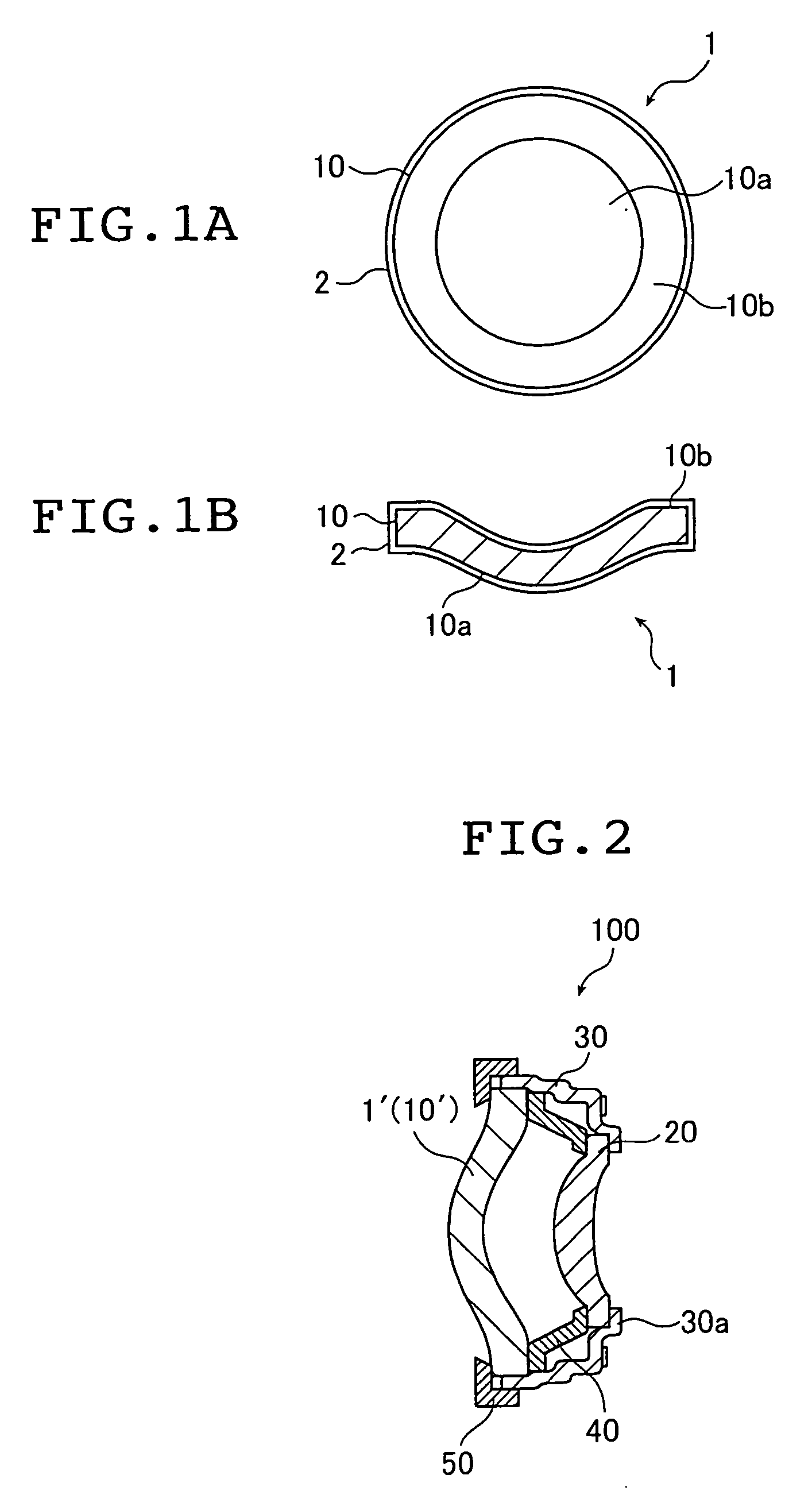
[0154] In this Example, an optical component was fabricated like the optical component 1 shown in FIG. 1. Briefly, a lens 10 was made of a polycarbonate resin as the optical component's body and, on all of its surfaces, a moisture-proof coating 2 was formed of an organic-inorganic hybrid layer.

Forming the Organic-Inorganic Hybrid Layer

[0155] Eight grams of SOANOL D2908 (ethylene-vinyl alcohol copolymer of Nippon Synthetic Chemical Industry Co., Ltd.) was dissolved in a solvent system consisting of 1-propanol (118.8 g) and water (73.2 g) at 80° C. To a portion (10.72 g) of the resulting solution, 2.4 ml of 2N HCl was added and the two were mixed. To the stirred solution, 1 g of tetraethoxysilane was added and the mixture was kept stirred for 30 minutes. The coating solution thus obtained was then applied to all surfaces of the lens (optical component's body) 10 with a wire bar. The applied coating was then dried at 120° C. for 5 minutes until an organic-inorganic hybrid layer form...

example 2

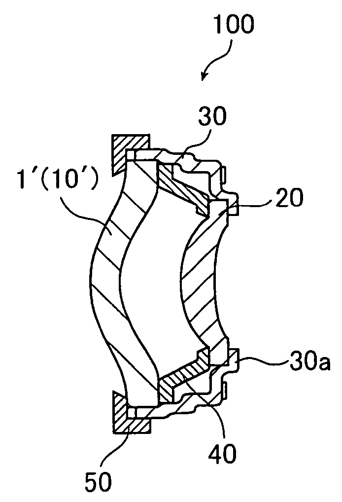
[0164] By repeating the procedure of Example 1 except that the flange portion 10b was masked during forming the organic-inorganic hybrid layer, an organic-inorganic hybrid layer was deposited in a thickness of 1 μm to form a moisture-proof coating 2 on all surfaces of the polycarbonate lens (optical component's body) 10 excepting the flange portion 10b. Thus the optical component 1′ was obtained. This sample was assembled as an optical component 1′ to make the optical unit 100 shown in FIG. 2 and its optical performance was evaluated. The results are also shown in Table 1.


PUM

PropertyMeasurementUnit
Lengthaaaaaaaaaa
Thicknessaaaaaaaaaa
Thicknessaaaaaaaaaa

Abstract

The present invention provides a plastic optical component. The plastic optical component has superior characteristics including lightweightness, low cost and suitability for mass production. The plastic optical component exhibits superior moisture barrier quality while experiencing no uneven refractive index profile in their interior even if they are subjected to the effect of water in the environment. An organic-inorganic hybrid layer obtained by a sol-gel process is formed as a moisture-proof coating at least on the surfaces of the plastic optical component's body which are in contact with the outside air.

Description

FIELD OF THE INVENTION [0001] This invention relates to the technical field of optical components such as lens and prism that are made of plastics, more particularly to plastic optical components that experience extremely small changes in optical performance due to moisture absorption. This invention also relates to an optical unit using such plastic optical components. [0002] Conventionally, camera lenses and a variety of lenses used in finders, copy equipment, printers, projectors and optical communications, as well as optical components including prisms, spectacle lenses, contact lenses and magnifiers are mostly manufactured from glass. [0003] However, with the recent progress in plastic materials and in the plastics molding technology, it has become possible to manufacture lenses, prisms and other optical components at low cost using plastics which are made from cheap materials, lightweight and suitable for mass production. [0004] The problem with plastics is that their optical ...

Claims


Application Information

Patent Timeline
IPC IPC(8): G02B3/00C08J7/043C08J7/048
CPCC08J7/047G02B1/105C08J2483/00G02B1/18C08J7/0427C08J7/048C08J7/043
Inventor SUZUKI, FUMIYUKIEIHA, NORIKO
Owner FUJIFILM HLDG CORP
Why Eureka
Try Eureka