Systems and methods for providing cooling in compressed air storage power supply systems

a technology of compressed air storage and power supply system, which is applied in the direction of domestic cooling equipment, lighting and heating equipment, machines/engines, etc., can solve problems such as windage losses, achieve the effects of reducing generator sizing, improving generator design flexibility, and reducing operating temperatur

Inactive Publication Date: 2006-03-23
ACTIVE POWER INC
View PDF62 Cites 70 Cited by
  • Summary
  • Abstract
  • Description
  • Claims
  • Application Information

AI Technical Summary

Benefits of technology

[0019] An advantage of the present invention is that the temperature of the gas being routed to the components and / or subsystems may be substantially lower than the heat-exchanging mediums (e.g., ambient air, oil, water, etc.) used by conventional heat exchangers. As a result, this correlates to a lower operating temperature not previously achieved in prior art cooling systems. A lower operating temperature promotes reduced generator sizing (e.g., smaller stator core and stator windings and smaller rotors) and increased generator design flexibility, and thus less cost. Moreover, reduced sizing further decreases spool-up time required for the turbine-generator to start producing emergency power. Another advantage of the present invention is that independent cooling systems, such as fans, compressors, oil circulating systems, are not needed to provide cooling. This correlates to less cost, elimination of a need to power such systems, elimination of maintenance, increased reliability, and a more compact system.
[0020] Another aspect of the present invention includes a power electronics housing which routes cool gas in direct contact with, or proximal to, the power electronics of the electrical generation system. The power electronics housing may include a thermally conductive body to which the power electronics are mounted and heat sinks. Cool gas derived in accordance with the principles of the invention may be routed through the thermally conductive body to extract heat generated by the power electronics during an active mode of operation of the electrical generation system. The heat sinks may extract heat from the power electronics during both standby and active modes of operation of the electrical generation system.
[0021] An advantage of cooling the power electronics with the expanded gas is that it increases the cooling capacity beyond that previously achieved with conventional cooling techniques, thereby permitting the power density of the power electronics to be increased to levels not previously sustainable by conventional cooling techniques.
[0022] Another aspect of the present invention includes stator housings which route cool gas in direct contact with, or proximal to, the wound stator core of an electrical generator. The stator housing may be machined to fit flush (e.g., air tight) against the stator core to maximize heat exchanging efficiency. Such stator housings may have one or more annular channels for routing cool gas around the stator. Stator housings may include a pressure sleeve to prevent gas from damaging the laminated stator core and / or windings or appurtenances thereof during power generation.

Problems solved by technology

The heat being removed by the cold gas may be generated by electrical resistance losses in the stator windings, hysteresis and / or eddy current losses in the laminated stator core, stray load losses on the rotor due to laminated stator core slot harmonics, and / or armature winding current harmonics, rotor windage losses, and friction losses in the bearings located within the electrical machine.

Method used


Image

  • Systems and methods for providing cooling in compressed air storage power supply systems
  • Systems and methods for providing cooling in compressed air storage power supply systems
  • Systems and methods for providing cooling in compressed air storage power supply systems

Examples


Embodiment Construction

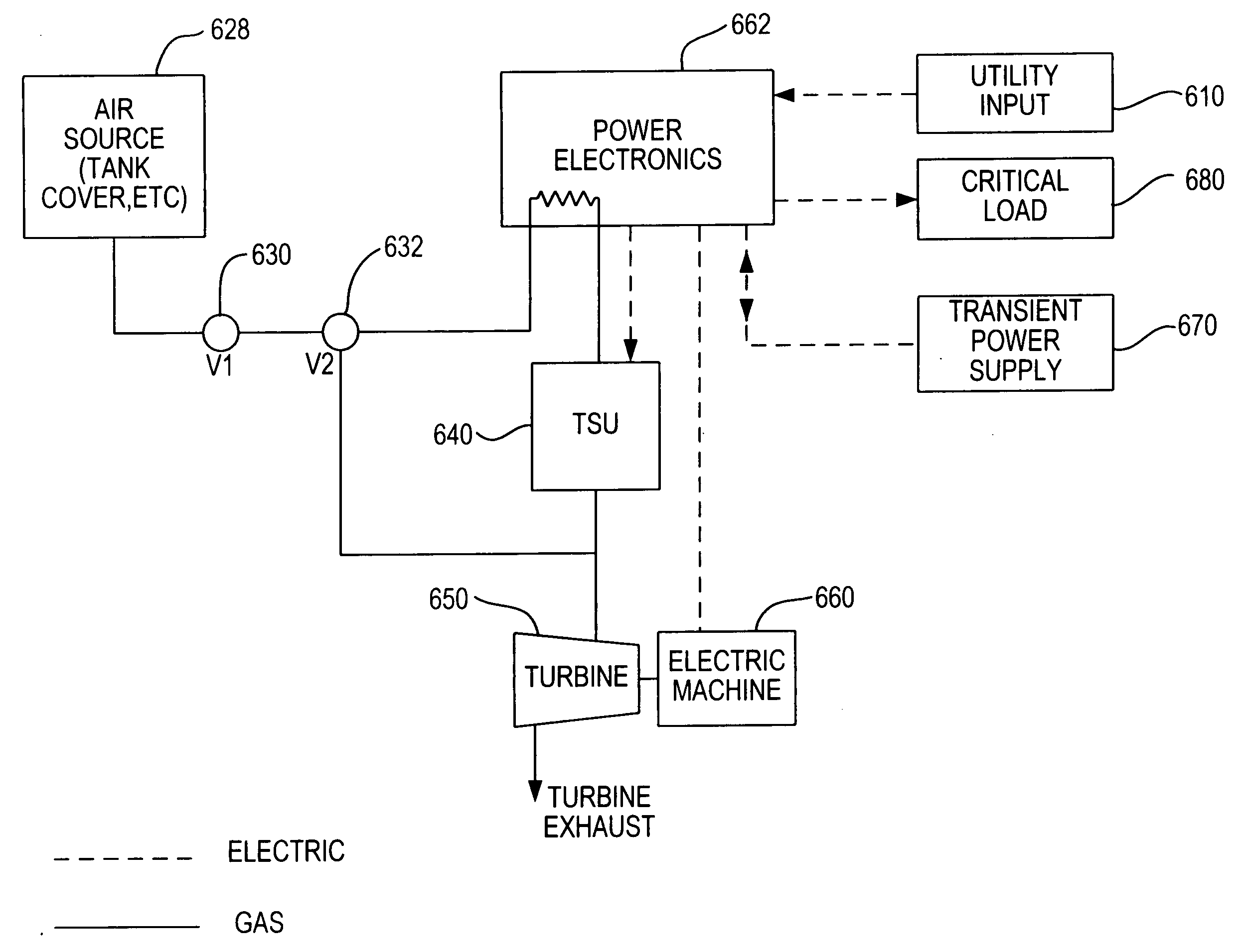
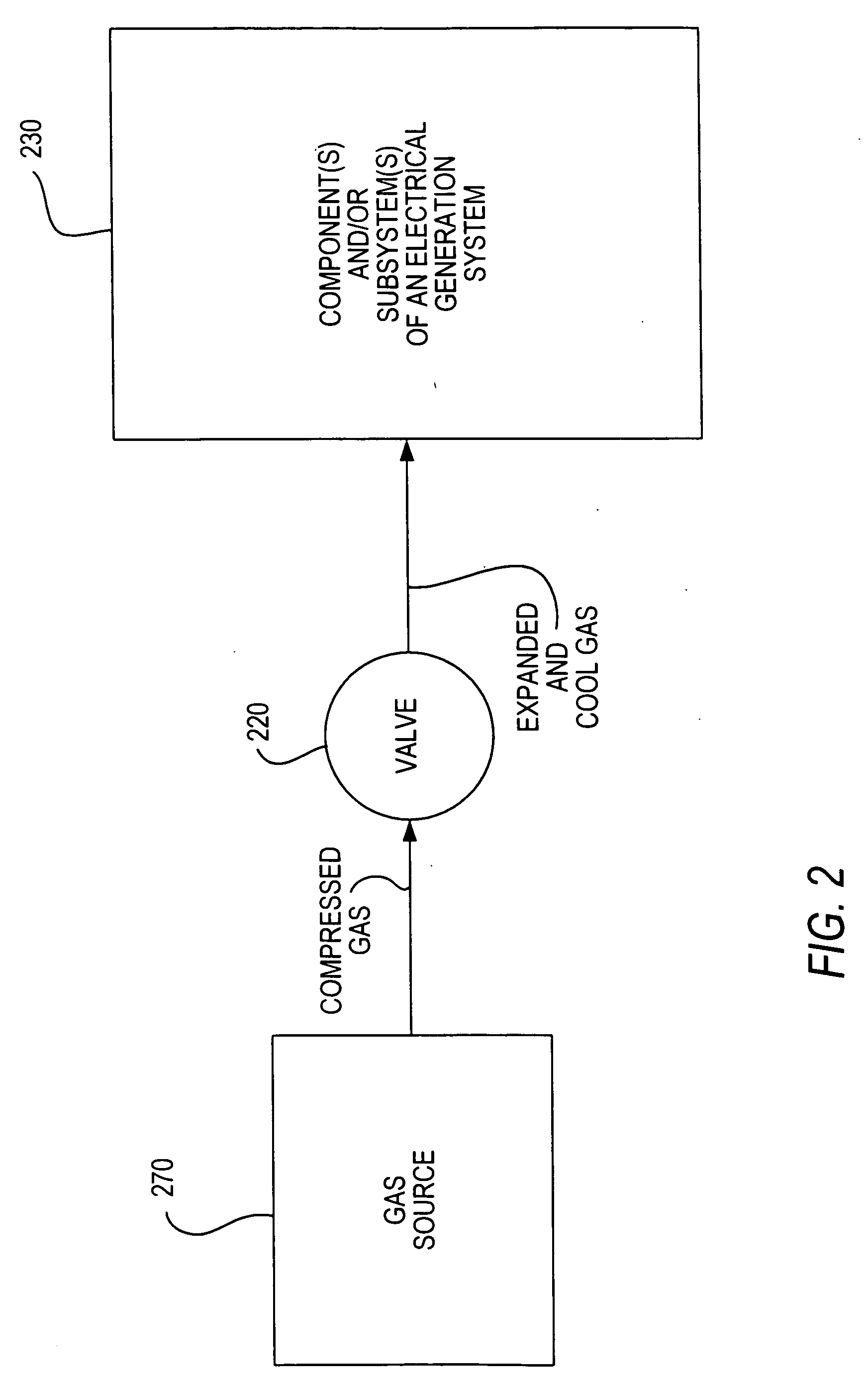
[0043] Cooling according to the principles of the present invention can be implemented in many different types of electrical generation systems, particularly systems that derive electrical power from stored compressed gas. Such systems include, but are not limited to, CAS systems and TACAS systems. To further facilitate understanding of the present invention, a brief discussion of such a system is provided to set forth a possible framework in which the invention may be practiced.

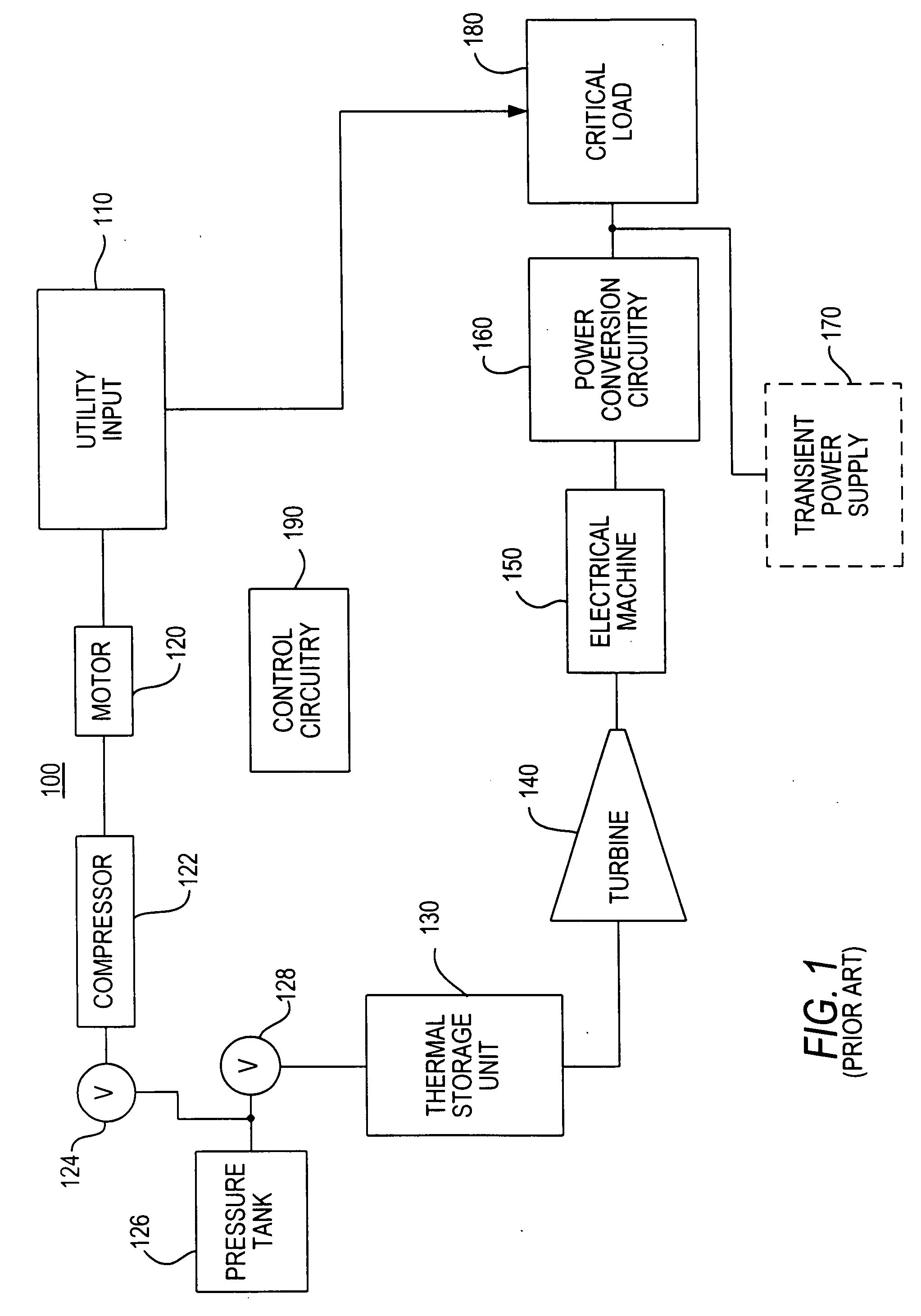
[0044]FIG. 1 shows a schematic of a known TACAS backup energy system 100. Backup energy system 100 may be connected to utility input 110 which supplies power to a critical load 180 during normal operating conditions. Persons skilled in the art will appreciate that utility input 110 may be any type of primary power source, AC or DC.

[0045] Backup energy system 100 includes motor 120, compressor 122, one way valve 124, pressure tank 126, valve 128, thermal storage unit 130, turbine 140, electrical machine 150...


PUM


Abstract

A system and method for cooling electrical machines (e.g., generators), sub-systems (e.g., power electronics), and components (e.g., bearings) in an electrical generation system such as a compressed air storage (CAS) energy system or a thermal and compressed air storage (TACAS) energy system is provided. Cooling is derived from the thermal expansion of a compressed gas, which may be the same gas used to drive a turbine-generator of CAS or TACAS energy system.

Description

BACKGROUND OF THE INVENTION [0001] This invention relates to systems and methods for removing heat from a system. More particularly, this invention provides heat exchanging techniques to remove heat from various components and / or subsystems of electrical generation systems such as thermal and compressed air storage (TACAS) backup energy systems or compressed air storage (CAS) backup energy systems. Electrical generation systems may include components and / or subsystems such as electrical machines and power electronics that may require cooling. [0002] Electrical machines such as generators and motors are well known in the art. Such machines are used in thousands of different applications, some of which include the generation of electric power. Electric power is generated, for example, when the rotor of a generator is driven by a prime mover (e.g., turbine) to produce a rotating magnetic field within the machine. The rotating magnetic field induces voltage within the stator windings of...

Claims


Application Information

Patent Timeline
Patent Type & Authority Applications(United States)
IPC IPC(8): F02G1/00F02G3/00F25B9/00F02C6/00F25D23/12F25D9/00
CPCH02K11/048H02K7/1823H02M7/00
Inventor RADKE, ROBERT E.LOGAN, SCOTT D.PERKINS, DAVID E.PINKERTON, JOSEPH F. III
Owner ACTIVE POWER INC
Why Eureka
Try Eureka