
High contrast optical path corrected screen

a technology of optical path and optical path, which is applied in the field of optical path corrected imaging screen, can solve the problems of reducing the contrast of the screen, reducing the quality of the image, and increasing so as to achieve the effect of improving the contrast, and reducing the cost of manufacturing

Inactive Publication Date: 2006-03-30
MASSACHUSETTS DEV FINANCE AGENCY
View PDF8 Cites 46 Cited by
  • Summary
  • Abstract
  • Description
  • Claims
  • Application Information

AI Technical Summary

Benefits of technology

[0010] The present invention provides rear projection screens that are thinner and that can be manufactured cheaply using roll-to-roll processes. The screens of the invention also offer increased throughput and higher contrast. By using planar materials having a differential refractive index, an optical element suitable for use in projection screens, having improved contrast and brightness, is provided. These flat screen components eliminate the need for an air gap between the light-redirecting array, e.g., Fresnel lens, and the other screen components, which thus reduces the screen thickness. This allows for the screen to be manufactured on a roll-to-roll process, that can significantly reduce the screen cost. By adding the capability of planarizing the elements, they can be combined in a final structure on a roll-to-roll process. Since the Fresnel lens can be combined with the lenticular lens before exposure of the black stripe region, the exposure of the black stripe region can account for any deviation from true collimation, de-centering, or non-normal angle of incidence of the light path in the projection system design.

Problems solved by technology

Current configurations provide air gaps in-between screen components that can accumulate dirt or dust, materials that degrade image quality.
The air gap also increases the cost of manufacturing, and the thickness of the system.
The traditional air gap used for Fresnel lenses used in projection TVs does not allow for lamination or combination of the Fresnel lens and other components in the screen.
However, this technology is also described as using an air gap, increasing the complexity of manufacturing, and the overall screen thickness.
Lamp life is an important issue with projection displays, and one method for increasing lamp life is to increase system throughput.
For example, the Fresnel lens has a fixed focal length, and any variation from this in design or production of the Fresnel lens, position of the projection lens, position of the light source, position of the folding or aspheric mirrors in the system can cause a significant amount of light to be absorbed by the contrast enhancing element.
If light is not perfectly collimated and parallel to the optic axis, then the black stripe regions may absorb more of the system intensity than is desired, thus reducing screen throughput.
With most system designs, the exact angle and degree of collimation of the light incident on the screen can vary, and designing each screen component to account for these variations individually can be cost prohibitive.
Fresnel reflections can also reduce the system throughput and can result in ghost images in certain situations.
The ability to reduce these reflections is limited because low-cost anti-reflection coating techniques typically require planarized surfaces.

Method used


Image

  • High contrast optical path corrected screen
  • High contrast optical path corrected screen
  • High contrast optical path corrected screen

Examples


example 1

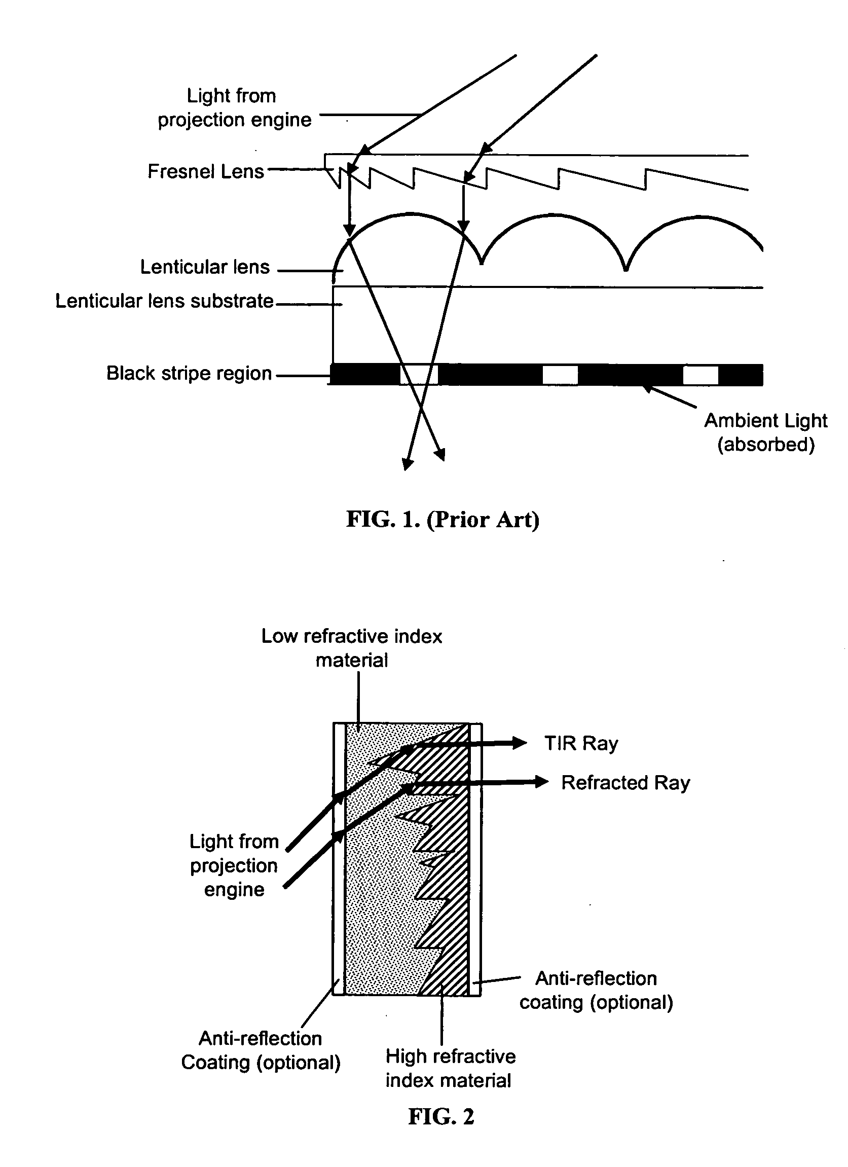
[0110] The planarized Fresnel lens of FIG. 3 can be created by casting a Fresnel lens structure into a high refractive index material such as Nitto Denko's high-refractive index thermosetting polymer capable of reaching a refractive index of 1.76 (See Nitto Denko Press Release, 11 Nov. 2003, at http: / / www.nitto.com / company / release / 03—11—11 / index.html). A planarization layer is coated onto the lens side of the planarized Fresnel lens and consists of a low refractive index material such as an aerogel. Since the planarized Fresnel lens has a substantially flat surface on either side, an anti-reflection coating can be applied to either side. The lens features should be designed to reflect or refract based on the refractive index differences between the high and low refractive index materials.

example 2

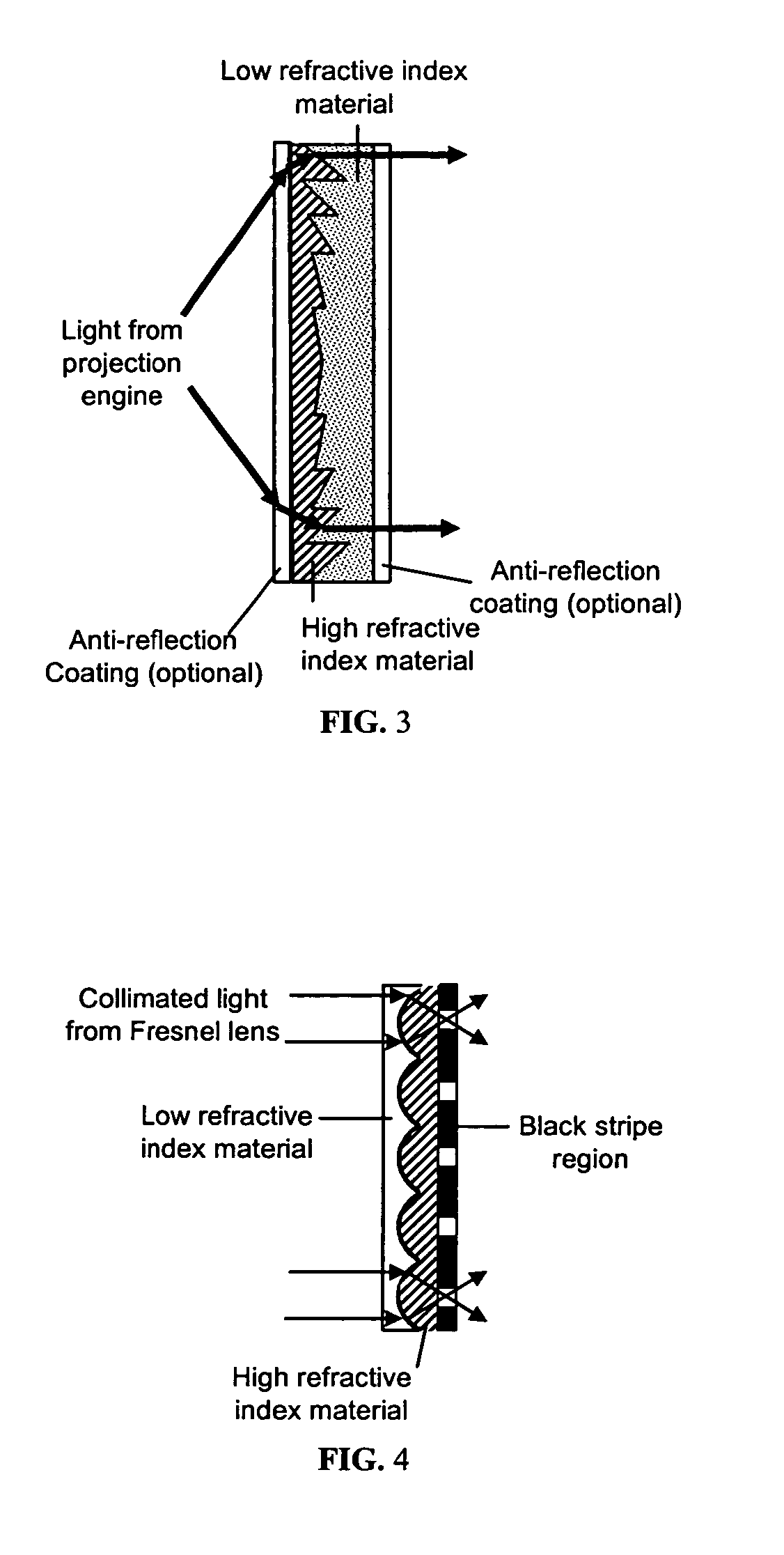
[0111] The planarized lenticular lens of FIG. 4 can be created by casting a lenticular lens structure into a high refractive index material such as Nitto Denko's high-refractive index thermosetting polymer capable of reaching a refractive index of 1.76 (See Nitto Denko Press Release, 11 Nov. 2003, at http: / / www.nitto.com / company / release / 03—11—11 / index.html). The lenticules should be designed to provide the correct focal distance, normally at the edge of the film, and the lenticules may be aspherical in shape. A planarization layer is coated onto the lens side of the planarized lenticular lens and consists of a low refractive index material such as an aerogels. An anti-reflection coating can be applied to the low refractive index side. A black stripe region is optically coupled to the high refractive index side of the planarized lenticular lens. This may be light sensitive material such as Chromalin from DuPont. After exposing to UV light, the Chromalin can be processed to create bla...

example 3

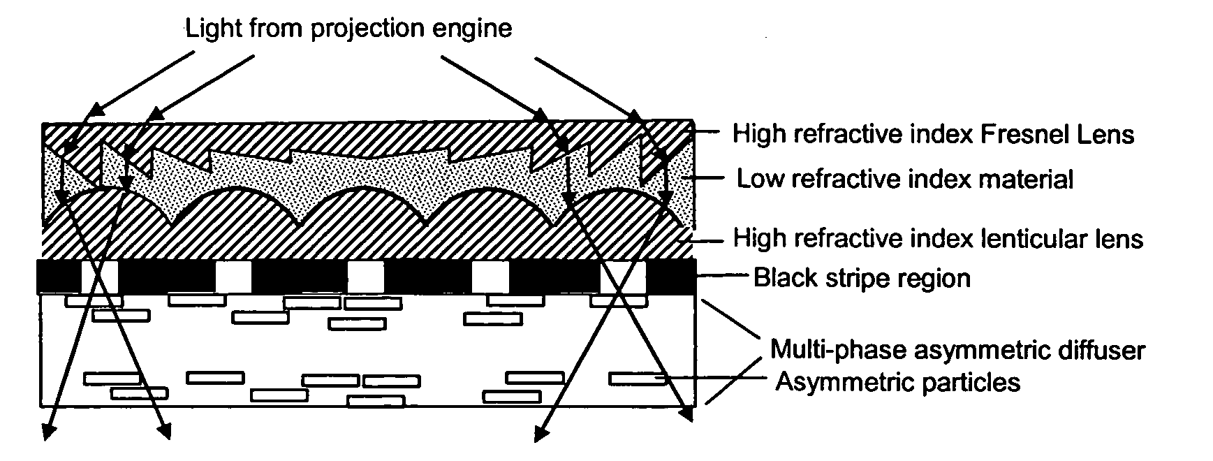
[0112] The high contrast optical path corrected screen of FIG. 9 can be created by casting the traditional Fresnel lens on a substrate that contains the planarized lenticular lens of Example 2. Other techniques such as embossing may be used. An asymmetric diffusion diffuser is optically coupled to the lenticular lens by lamination. A light sensitive material such as Chromalin from DuPont is optically coupled to the asymmetric diffuser. Diverging light from UV light source is directed toward the Fresnel lens. The light source is positioned in a location and directed at an angle to the screen that simulates the angle and direction of the light from the end-use projection engine. The light is refracted / reflected to near collimation by the Fresnel lens and directed to the planarized lenticular lens. The planarized lenticular lens focuses the light in the horizontal direction into the asymmetric diffuser. The asymmetric diffuser spreads the light in the vertical direction and does not su...


PUM


Abstract

By using high and low refractive index materials, a planarized reflective-refractive Fresnel lens and a planarized refractive lenticular lens can be created. These flat screen components eliminate the need for an air-gap, thus reducing the screen thickness. Additionally, this allows for the screen to be manufactured on a roll-to-roll process that can significantly reduce the screen cost. By adding the capability of planarizing the elements, they can be combined in a final structure on a roll-to-roll process. Since the Fresnel lens can be combined with the lenticular lens before exposure of the black stripe region, the exposure of the black stripe region can account for any deviation from true collimation or non-normal angle of incidence of the light path in the projection system design.

Description

RELATED APPLICATIONS [0001] This application claims the benefit of priority under 35 U.S.C. 119(e) to copending U.S. Provisional Application Nos. 60 / 609,437, filed on Sep. 13, 2004, the entire contents of which is incorporated herein by reference. Related applications are Ser. Nos. 11 / 197,246 and 11 / 200,592, the entire contents of which are incorporated herein by reference.FIELD OF THE INVENTION [0002] The invention generally relates to imaging screen elements, an optical path corrected imaging screen and methods of manufacture. BACKGROUND OF THE INVENTION [0003] Screen components in projection TVs need to be reduced in thickness, to reduce total screen costs and create a thinner form factor, i.e., reduce bulk. Current configurations provide air gaps in-between screen components that can accumulate dirt or dust, materials that degrade image quality. The air gap also increases the cost of manufacturing, and the thickness of the system. [0004] The traditional air gap used for Fresnel ...

Claims


Application Information

Patent Timeline
Patent Type & Authority Applications(United States)
IPC IPC(8): G03B21/56
CPCG02B3/0031G03B21/625G02B3/08G02B3/0068
Inventor YEO, TERENCE E.COLEMAN, ZANE A.
Owner MASSACHUSETTS DEV FINANCE AGENCY
Features
  • Generate Ideas
  • Intellectual Property
  • Life Sciences
  • Materials
  • Tech Scout
  • Unparalleled Data Quality
  • Higher Quality Content
  • 60% Fewer Hallucinations
Learn More