ND filter, manufacturing method thereof, and aperture device

a technology of aperture device and nd filter, which is applied in the direction of natural mineral layered products, instruments, transportation and packaging, etc., can solve the problems of high cost of lower-oxide target, deformation of substrate or film, and excessive amount of light entering the light-sensitive surface, etc., to improve the productivity of nd filter, excel in the neutrality in a visible range, and improve the reliability

Inactive Publication Date: 2006-03-30
COPAL CO LTD
View PDF5 Cites 13 Cited by
  • Summary
  • Abstract
  • Description
  • Claims
  • Application Information

AI Technical Summary

Benefits of technology

[0016] The inventive method deposits a light-absorbing film and a dielectric film on a resin film traveling at a constant speed to obtain a thin film ND filter. Typically, the roll coating method is used to alternately deposit the light-absorbing film and the dielectric film by feeding the resin film to improve the productivity of ND filter. The light-absorbing film deposition employs the sputtering method using metal (M) or a mixture of metal (M) and metal oxide (MOx) as a target and a mixture gas of oxygen, nitrogen, and argon as an ambient gas. This makes it possible to obtain the composition of the light-absorbing film excellent in the reliability. The light-absorbing film obtained in this manner is controlled so as to keep its extinction coefficient to be 0.3 or more. On the other hand, the sputtering method or the vacuum evapor...

Problems solved by technology

Generally, when the brightness of an object is too high for an imaging system such as a camera and a video, although minimizing an aperture stop (minimizing an aperture diameter), an excessive amount of light may enter into a light-sensitive surface.
When a resin film is used as the substrate, applying a process temperature over ...

Method used


Image

  • ND filter, manufacturing method thereof, and aperture device
  • ND filter, manufacturing method thereof, and aperture device
  • ND filter, manufacturing method thereof, and aperture device

Examples


Embodiment Construction

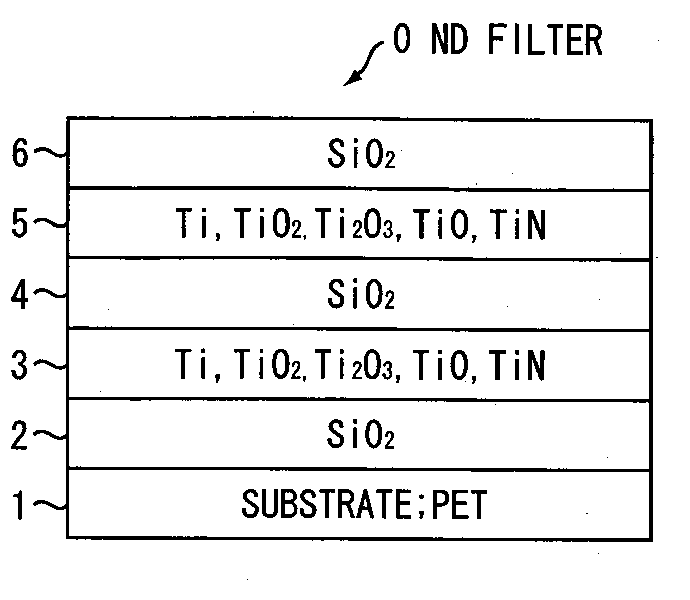
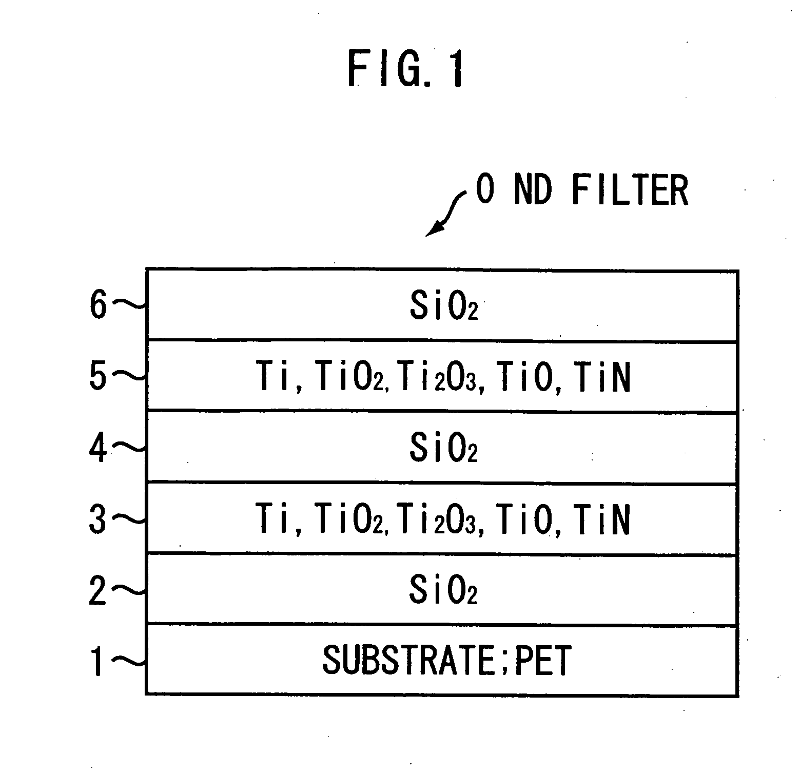
[0022] Embodiments of the present invention will be described in further detail with reference to the accompanying drawings. FIG. 1 is a schematic sectional view showing the configuration of a thin film ND filter according to the present invention. As shown in FIG. 1, an ND filter 0 is a thin film type formed by laminating light-absorbing films 3 and 5 and dielectric films 2, 4, and 6 on a transparent substrate 1. Characteristically, the transparent substrate 1 is composed of a resin film that can be fed at a constant speed. The light-absorbing films 3 and 5 are composed of a mixture of a metal and a metallic compound. The light-absorbing films 3 and 5 are deposited by sputtering with ambient gas, i.e., a mixture gas of oxygen, nitrogen, and argon, to the constantly traveling film 1 while using a target composed of simple metal or a mixture of metal and metal oxide. The light-absorbing films 3 and 5 provide the extinction coefficient of 0.3 or more in the visible range by controllin...


PUM

PropertyMeasurementUnit
Temperatureaaaaaaaaaa
Fractionaaaaaaaaaa
Fractionaaaaaaaaaa

Abstract

An ND filter of a thin film type is formed on a transparent substrate, such that a light-absorbing film and a dielectric film are laminated on the transparent substrate. The transparent substrate is formed of a resin film which can be fed at a constant speed. The light-absorbing film is deposited by sputtering a target material comprised of a metal or a mixture of a metal and a metal oxide onto the resin film traveling at the constant speed while using a mixture gas of oxygen, nitrogen, and argon as an ambient gas. Consequently, the light-absorbing film is composed of a mixture of the metal and metal compounds, and has an extinction coefficient of 0.3 or more in a visible wavelength range. Typically, the light-absorbing film is composed of 1% through 50% by weight of the metal, 30% or more by weight of saturated metal oxide, and residual components composed of the compounds of the metal containing lower oxide and nitride of the metal.

Description

BACKGROUND OF THE INVENTION [0001] 1. Technical Field [0002] The present invention relates to an ND filter and a manufacturing method thereof. The ND (neutral density) filter is used for absorbing the amount of incident light so as to uniformly decrease the amount of transmissive light over an entire visible range. [0003] 2. Related Art [0004] Generally, when the brightness of an object is too high for an imaging system such as a camera and a video, although minimizing an aperture stop (minimizing an aperture diameter), an excessive amount of light may enter into a light-sensitive surface. To solve this problem, it is a common practice to attach an ND filter to a part of the imaging system so as to limit the amount of light incident on the light-sensitive surface. In this case, the ND filter has spectral characteristics of simply decreasing the amount of incident light and therefore needs to ensure uniform transmittance over an entire visible wavelength range. [0005] Until now, a pl...

Claims


Application Information

Patent Timeline
IPC IPC(8): B32B15/04C23C14/00B32B19/00
CPCC23C14/54C23C14/562C23C14/545Y10T428/31678
Inventor KUNII, KOKI
Owner COPAL CO LTD
Why Eureka
Try Eureka