Frequency controller for a monolithic clock generator and timing/frequency reference

Active Publication Date: 2006-04-06
INTEGRATED DEVICE TECH INC
View PDF4 Cites 27 Cited by
  • Summary
  • Abstract
  • Description
  • Claims
  • Application Information

AI Technical Summary

Benefits of technology

[0009] In various exemplary embodiments, the invention provides a frequency controller and a temperature compensator for use in providing open-loop frequency control and selection for a low-jitter, free-running and self-referencing clock generator and/or a timing and frequency reference which is highly accurate over PVT and aging (time) variations and which can be integrated monolithically with other circuitry, to form a singular integrated circuit. No separate reference oscillator is required. The various exemplary embodiments of the invention include features for highly accurate frequency generation over fabrication process, voltage, and temperature (“PVT”) variations. These features include frequency tuning and select

Problems solved by technology

The difficulty with such crystal oscillators is that they cannot be fabricated as part of the same integrated circuit (“IC”) that is to be driven by their clock signal.
For example, because such a processor must be connected through outside circuitry (such as on a printed circuit board (PCB)), power dissipation is comparatively increased.
In applications which rely on a finite power supply, such as battery power in mobile communications, such additional power dissipation is detrimental.
In addition, such non-integrated solutions, by requiring an additional IC, increase space and area requirements, whether on the PCB or within the finished product, which is also detrimental in mobile environments.
Moreover, such additional components increase manufacturing and production costs, as an additional IC must be fabrica

Method used


Image

  • Frequency controller for a monolithic clock generator and timing/frequency reference
  • Frequency controller for a monolithic clock generator and timing/frequency reference
  • Frequency controller for a monolithic clock generator and timing/frequency reference

Examples


Embodiment Construction

[0069] While the present invention is susceptible of embodiment in many different forms, there are shown in the drawings and will be described herein in detail specific examples and embodiments thereof, with the understanding that the present disclosure is to be considered as an exemplification of the principles of the invention and is not intended to limit the invention to the specific examples and embodiments illustrated.

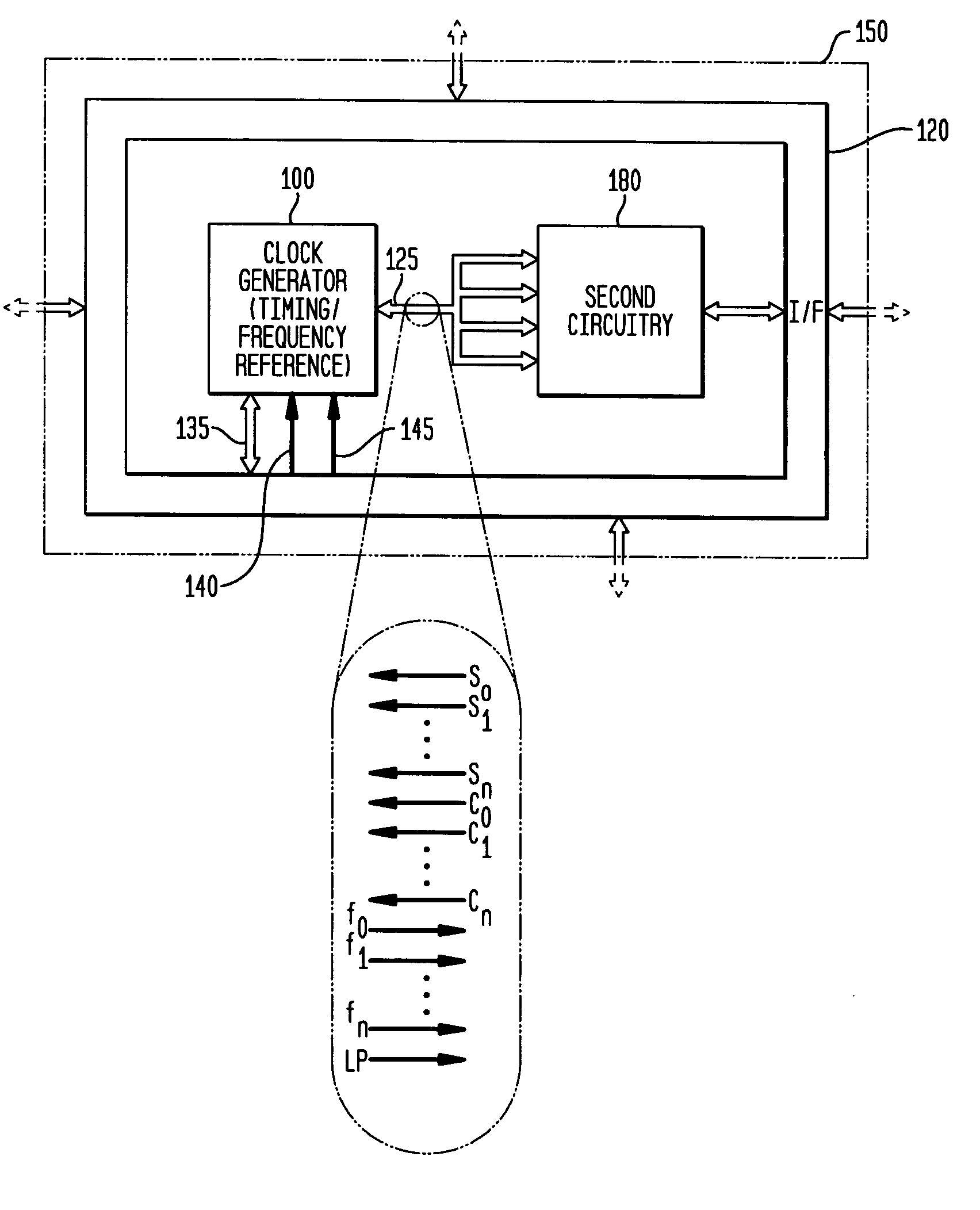
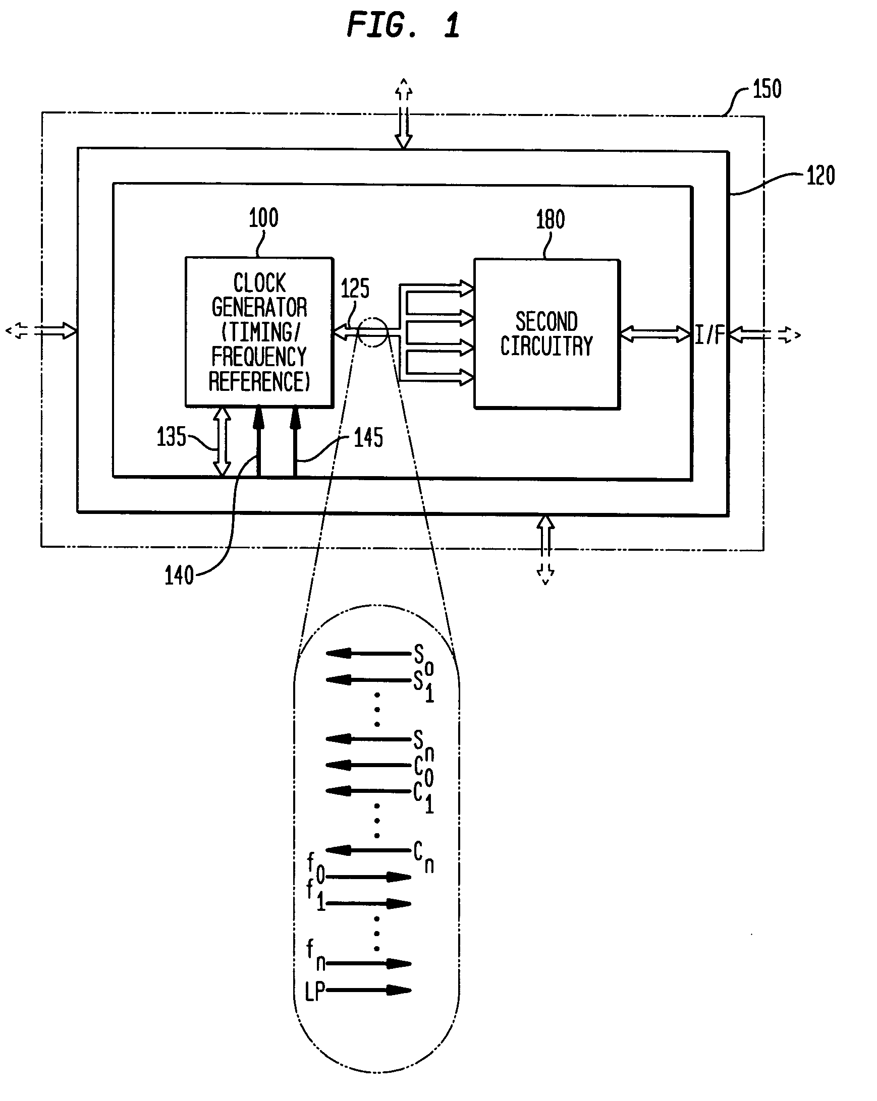
[0070] As indicated above, the various embodiments of the invention provide numerous advantages, including the ability to integrate a highly accurate (over PVT and age), low-jitter, free-running and self-referencing clock generator and / or a timing and frequency reference with other circuitry, such as illustrated in FIG. 1. FIG. 1 is a block diagram illustrating an exemplary system embodiment 150 in accordance with the teachings of the present invention. As illustrated in FIG. 1, the system 150 is a single integrated circuit, having a clock generator and / or timing...


PUM


Abstract

In various embodiments, the invention provides a frequency controller to control and provide a stable resonant frequency of a clock generator and/or a timing and frequency reference. Such stability is provided over variations in a selected parameter such as temperature and fabrication process variations. The various apparatus embodiments include a sensor adapted to provide a signal in response to at least one parameter of a plurality of parameters; and a frequency controller adapted to modify the resonant frequency in response to the second signal. In exemplary embodiments, the sensor is implemented as a current source responsive to temperature fluctuations, and the frequency controller is implemented as a plurality of controlled reactance modules which are selectively couplable to the resonator or to one or more control voltages. The controlled reactance modules may include fixed or variable capacitances or inductances, and may be binary weighted. Arrays of resistive modules are also provided, to generate one or more control voltages.

Description

CROSS-REFERENCE TO RELATED APPLICATIONS [0001] This application is a continuation-in-part of and claims priority to U.S. patent application Ser. No. 11 / 084,962, filed Mar. 21, 2005, inventors Michael Shannon McCorquodale, Scott Michael Pemia, and Amar Sarbbaseh Basu, entitled “Monolithic Clock Generator and Timing / Frequency Reference” (the “first related application”), which is commonly assigned herewith, the contents of which are incorporated herein by reference, and with priority claimed for all commonly disclosed subject matter, and further claims priority to U.S. Provisional Patent Application Ser. No. 60 / 555,193, filed Mar. 22, 2004, inventor Michael Shannon McCorquodale, entitled “Monolithic and Top-Down Clock Synthesis with Micromachined Radio Frequency Reference” (the “second related application”), which is commonly assigned herewith, the contents of which are incorporated herein by reference, and with priority claimed for all commonly disclosed subject matter. [0002] This a...

Claims


Application Information

Patent Timeline
IPC IPC(8): H03L1/00
CPCH03B5/06H03B2201/025H03L1/022H03L3/00H03L7/08H03L7/0812H03L7/099H03B5/1228H03B5/1212H03B5/124
Inventor MCCORQUODALE, MICHAEL SHANNONPERNIA, SCOTT MICHAELKUBBA, SUNDUS
Owner INTEGRATED DEVICE TECH INC
Why Eureka
Try Eureka