Microfabricated diffusion-based chemical sensor

Inactive Publication Date: 2006-04-06
UNIV OF WASHINGTON
View PDF64 Cites 13 Cited by
  • Summary
  • Abstract
  • Description
  • Claims
  • Application Information

AI Technical Summary

Benefits of technology

[0013] Microfluidic devices allow one to take advantage of diffusion as a rapid separation mechanism. Flow behavior in microstructures differs significantly from that in the macroscopic world. Due to extremely small inertial forces in such structures, practically all flow in microstructures is laminar. This allows the movement of diff

Problems solved by technology

None of the foregoing publications describe a channel system capable of analyzing small particles in very small quantities o

Method used


Image

  • Microfabricated diffusion-based chemical sensor
  • Microfabricated diffusion-based chemical sensor
  • Microfabricated diffusion-based chemical sensor

Examples


example 1

Fabrication of Channel Cell

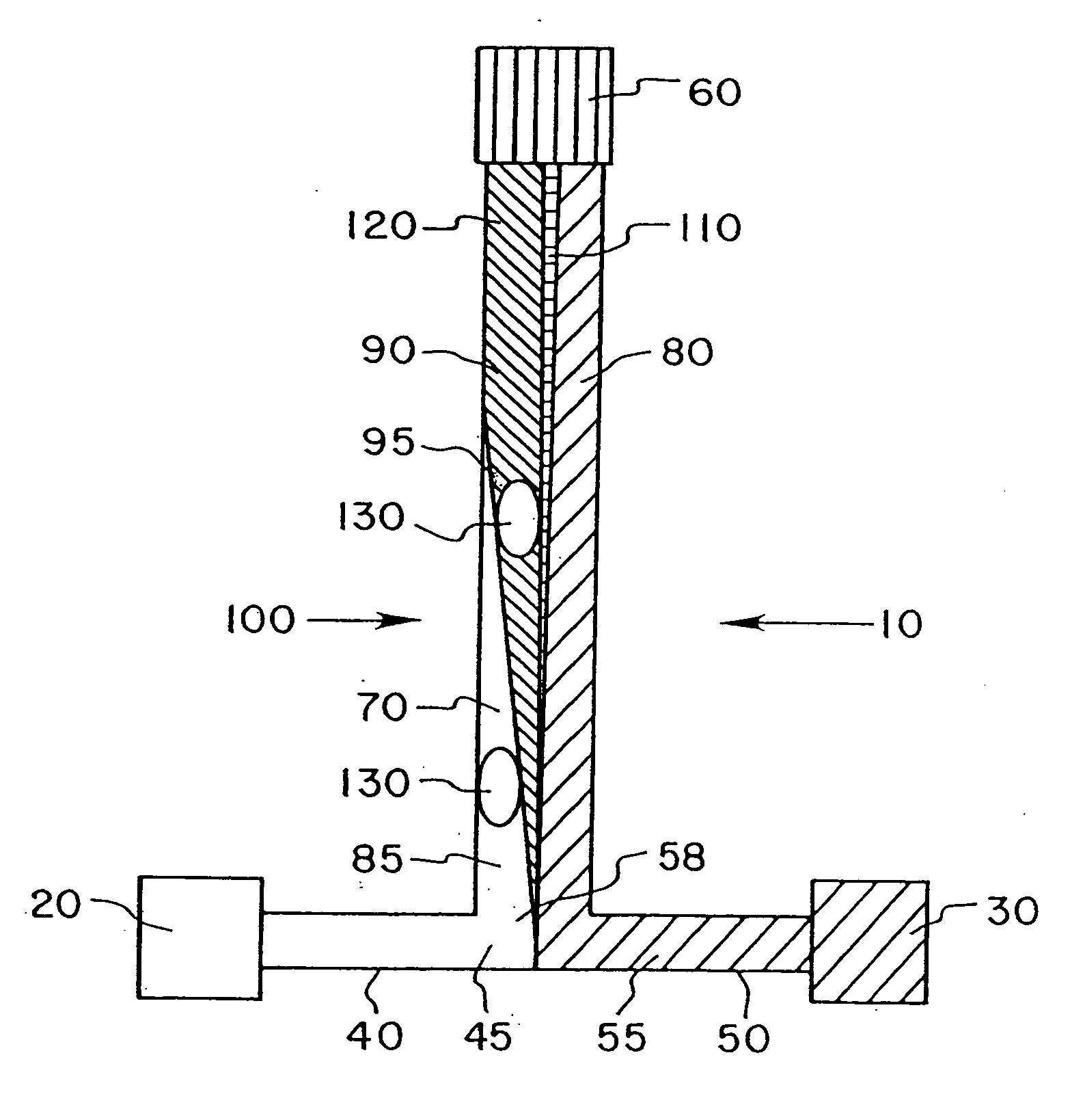
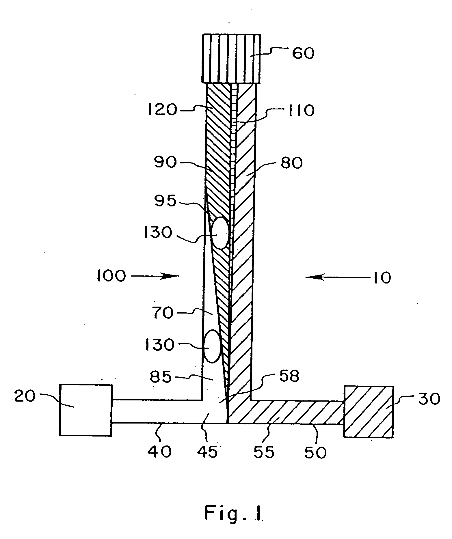
[0130] A two-mask level process was used to fabricate a channel cell of this invention on a silicon wafer. The channel cell had a flow channel 400 micrometers wide and 20 mm long. The “branches” or crossbar of the “T” comprising the inlet channels was a groove 30 mm long and 200 micrometers wide. Channel depth was 50 micrometers.

[0131] The first mask level defined the inlets and outlet ports, which were etched completely through the wafer to the rear side of the silicon. The second level defined the fluid transport channels.

[0132] Four inch chrome masks were made to these specifications by Photo Sciences, Inc. (Torrance, Calif.) and 3″ wafers ({100}, n-type) with 500 nm of SiO2 grown on them were used.

[0133] Wafers were cleaned in a Piranha bath (H2SO4 and H2O2) (2:1) before processing. A primer (HMDS spun on at 3000 rpm) was used to enhance photoresist adhesion. About one μm of AZ-1370-SF (Hoechst) photoresist was deposited by spin coating (3000 rpm),...

example 2

Fluorescence Color Changes with pH

[0139] Five 0.01 M HEPES Buffer solutions, with pH 7.2, 7.4, 7.6, 7.8 and 8.0 were prepared from analytical grade chemicals (Aldrich). The resulting solutions were used consecutively as sample streams. The analyte in question in this experiment is H+ or OH−. 1 mg of the fluorescent pH indicator dye carboxy-SNAFL 2 (Molecular Probes, Eugene, Oreg.), was dissolved in 2 ml of DMSO (((0.9%, Aldrich). 0.1 ml of this solution was mixed with 1 ml of a 0.0001 M HEPES Buffer of pH 7.0. The resulting solution was used as the indicator stream.

[0140] The T-sensor channel cell was attached to the stage of a microscope so that the joint of the T-sensor was in the view field of the objective. The inlet ports and the outlet port were connected to injector loops and to upright tubes which were filled with water so that there was a pressure difference of 30 mm water column between the inlet ports and the outlet port. Both inlet ports were exposed to identical press...

example 3

Kinetic Measurements as a Function of Distance

[0143] Alkaline phosphatase in serum and 0.1 M p-nitrophenol phosphate (PNPP)(weakly yellow) in 0.1 M HEPES buffer, pH 7.40, were injected into a T-sensor device. The alkaline phosphatase catalyzed the reaction of PNPP to p-nitrophenol (strongly yellow) and phosphate. The formation, (and rate thereof), of p-nitrophenol was detected by an increase in yellow color. The rate of change of yellow color intensity as a function of distance from the T-joint was a function of enzyme concentration, enabling calculation of a rate constant.


PUM


Abstract

A channel-cell system is provided for detecting the presence and/or measuring the presence of analyte particles in a sample stream comprising: a) a laminar flow channel; b) two inlet means in fluid connection with said laminar flow channel for respectively conducting into said laminar flow channel (1) an indicator stream which may comprise an indicator substance which indicates the presence of said analyte particles by a detectable change in property when contacted with said analyte particles, and (2) said sample stream; c) wherein said laminar flow channel has a depth sufficiently small to allow laminar flow of said streams and a length sufficient to allow particles of said analyte to diffuse into said indicator stream to the substantial exclusion of said larger particles in said sample stream to form a detection area; and d) outlet means for conducting said streams out of said laminar flow channel to form a single mixed stream.

Description

CROSS-REFERENCE TO RELATED APPLICATIONS [0001] This application is a continuation of U.S. application Ser. No. 09 / 426,683 filed Oct. 25, 1999, which is a continuation of U.S. application Ser. No. 08 / 829,679 filed Mar. 31, 1997, now U.S. Pat. No. 5,972,710 issued Oct. 26, 1999, which is a continuation-in-part of U.S. application Ser. No. 08 / 625,808 filed Mar. 29, 1996, now U.S. Pat. No. 5,716,852 issued Feb. 10, 1998. This application also claims priority to U.S. application Ser. No. 09 / 703,764 filed Nov. 1, 2000, which is a continuation-in-part of co-pending application Ser. No. 09 / 500,398, filed Feb. 8, 2000, a continuation of application Ser. No. 09 / 346,852 filed Jul. 2, 1999, which is a divisional application of application Ser. No. 08 / 663,916 filed Jun. 14, 1996, now U.S. Pat. No. 5,932,100 issued Aug. 3, 1999, claiming priority to application No. 60 / 000,261 filed Jun. 16, 1995, all of the foregoing applications being incorporated herein by reference to the extent not inconsiste...

Claims


Application Information

Patent Timeline
IPC IPC(8): G01N33/00
CPCA61M1/14B01D11/0492B01D11/0496B01L3/5027B01L3/502761B01L3/502776Y10T436/25375B01L2300/0816B01L2300/0867B01L2400/0406B01L2400/0487G01N15/1484B01L2200/0636
Inventor WEIGL, BERNHARD H.YAGER, PAUL
Owner UNIV OF WASHINGTON
Why Eureka
Try Eureka