Adaptive beam forming receiver

a beam forming receiver and beam technology, applied in the field of wireless communication systems, can solve the problems of multipath interference effects, wlan performance can be greatly degraded, wlans often fall short of the expected operating range, etc., and achieve the effect of simplifying the interface, facilitating adaptation to different signal formats and signal characteristics

Inactive Publication Date: 2006-04-06
RENDA TRUST
View PDF1 Cites 23 Cited by
  • Summary
  • Abstract
  • Description
  • Claims
  • Application Information

AI Technical Summary

Benefits of technology

[0025] In an embodiment of the present invention, the weight amplitude controlled by the second AGC loop is substituted by weight normalization embedded hardware to provide faster convergence. Additionally, a feedback mechanism in the weight normalization is used to prevent integrator (low pas filter) overflow for the error signal.
[0026] In the present invention, the antenna weights and combining are performed at the RF frequency, RF combining, instead of at the baseband. Accordingly, in an embodiment of the present invention, a beam former is located between the antenna and the receiver / transmitter interface. RF combining simplifies the interface between the beam former and the transmitter / receiver. Typically, this interface is the same for most vendors whereas the baseband interface differs from vendors to vendors. Accordingly, the approach of the present invention enables beam former processing to be compatible with most vendors.
[0027] In the present invention, closed loop blind beamforming is employed. The closed loop operation is continuously active with or without the presence of signal and / or interference. In contrast to an open loop implementation, in which signal detection, acquisition, synchronization are required before the beamforming operation can be performed, closed loop implementation requires minimum amount of preprocessing and control. The present invention operates on signal power and noise characteristics only. Accordingly, no additional signal format information is needed. Thus, the prevent invention can be easily adapted to different signal format and signal characteristics. This allows the present invention to be applied to a wide variety of wireless systems such as WiMax, cellular phone system, and satellite radio and / or video broadcast system.
[0028] The present invention provides substantial increase in operating range in a multipath-rich environment; an adaptive antenna null formation, which suppresses the interference arriving from directions other than the desired signal; a reduced deployment effort; cost effectiveness; power efficiency; process, temperature, component variation insensitivity; compactness; fast convergence; and compatibility with existing WLAN systems by exploiting the spatial and polarization antenna diversity and optimal signal combining.

Problems solved by technology

It has been found that WLANs often fall short of the expected operating range when actually deployed.
In particular, WLAN performance can be greatly degraded by direct and multipath radio interference.
Similarly, in any indoor wireless system, multipath interference effects occur when the transmitted signal is reflected from objects such as walls, furniture, and other indoor objects.
The channel re-use factor imposes a severe restriction on implementation of 802.11b / g based systems which requires significantly more effort in the network deployment, and increases the chances of interference and packet collision especially within an environment with a dense user cluster, such as in an office building or apartment building.
Multipath interference further complicates the situation because being physically closer to an AP does not mean the signal from the AP is stronger.
The drawback of the selection diversity approach using a single shared receiver is that fast antenna switching and signal quality comparison is required.
The proposed approach can be unstable in some cases and unable to achieve fast convergence and integrator overflow.
The use of digital signal processing techniques for any solution involving multiple antenna elements uses high power and has high costs.
Since each antenna element requires two high-speed analog to digital converters (ADC), a solution involving four antenna elements would use eight high speed ADCs, thereby having higher cost and higher power consumption.
Alternatively, analog implementations are typically complicated by poor component tolerances and high IC process and temperature-dependent parameter variations.

Method used


Image

  • Adaptive beam forming receiver
  • Adaptive beam forming receiver
  • Adaptive beam forming receiver

Examples


Embodiment Construction

[0044] Reference will now be made in greater detail to a preferred embodiment of the invention, an example of which is illustrated in the accompanying drawings. Wherever possible, the same reference numerals will be used throughout the drawings and the description to refer to the same or like parts.

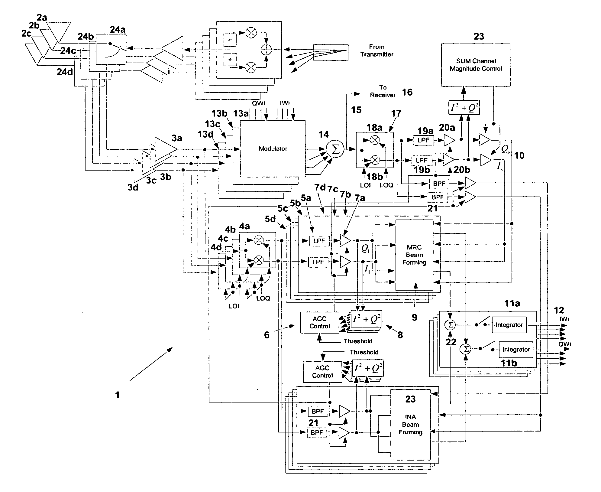
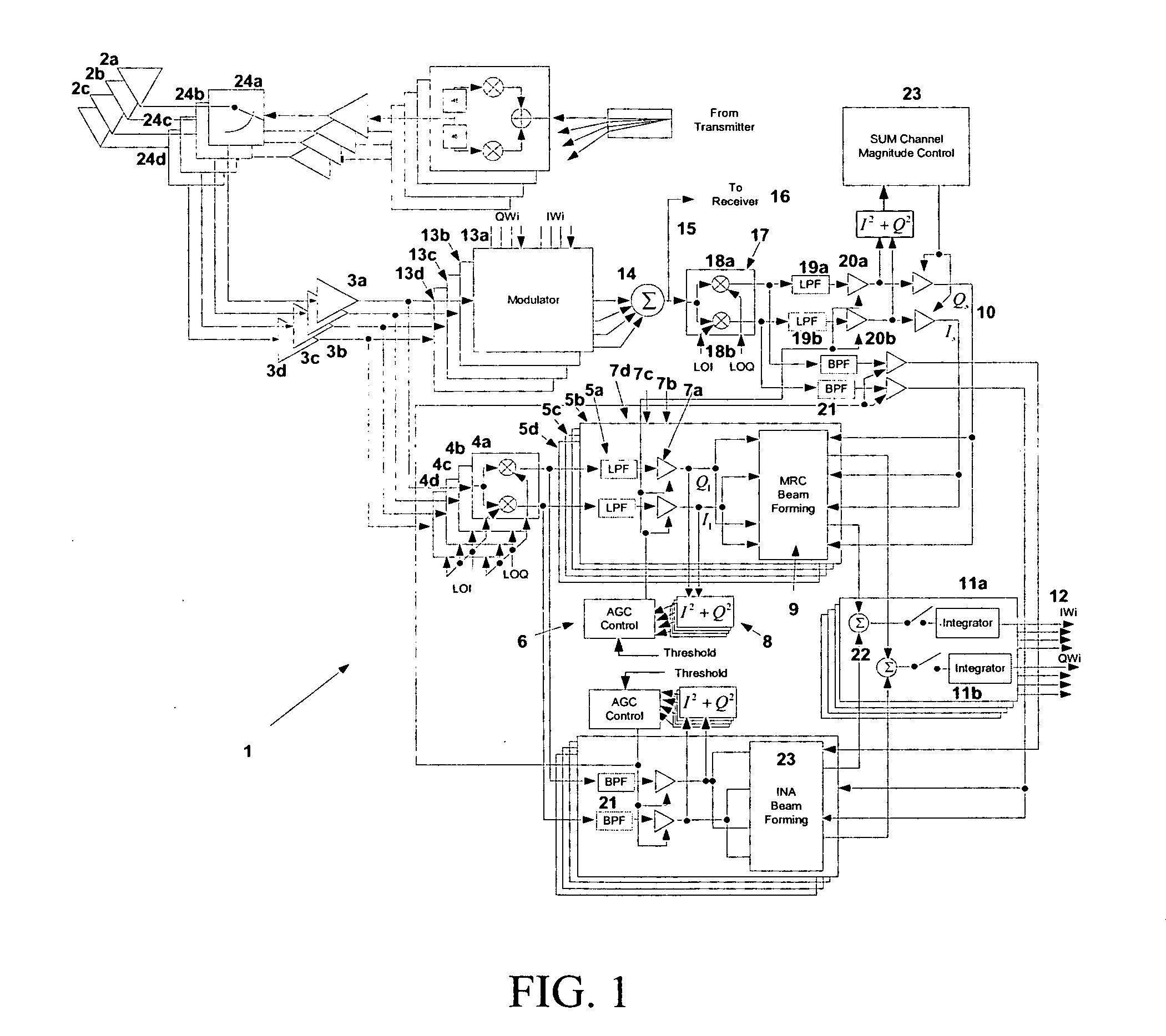
[0045]FIG. 1 shows a conventional method for beamforming system disclosed in U.S. patent application Ser. No. 10 / 732,003, filed Dec. 10, 2003, Wireless Communication System Using a Plurality of Antenna Elements with Adaptive Weighting and Combining Techniques. It is an illustration of wireless receive beam forming system including closed loop implementation of MRC (maximal ratio combining) and INA (interference nulling algorithm) for performing simultaneously signal combining and interference cancellation. Within wireless receive beam forming system 1 is a plurality of antennas 2a-d and along which wireless receive beam forming system 1 may receive (or transmit) signals. In this example,...


PUM


Abstract

The present invention provides a method and system for operating a wireless communication system in which received signals from a plurality of antennas are weighted and combined with a beam forming operation to form an output signal. In an embodiment of the present invention, beamforming operations are performed with maximal ratio combining (MRC) and an interference nulling algorithm (INA). The INA receives an error signal which is 180° out of phase with a combination of the channels for individual antennas, referred to as the SUM channel. The error signal is determined by complex conjugate multiplication of the individual signals and a reference complex signal. The weight amplitude is controlled by weight normalization to provide faster convergence and prevent integrator overflow.

Description

CROSS REFERENCE TO RELATED APPLICATION [0001] This application claims the benefit of U.S. patent application Ser. No. 10 / 732,003, filed Dec. 10, 2003, the entirety of which is hereby incorporated by reference into this application.BACKGROUND OF THE INVENTION [0002] 1. Field of the Invention [0003] This invention relates generally to wireless communication systems. More particularly, it relates to a wireless communication system using a plurality of antenna elements with weighting and combining techniques for optimizing antenna diversity and combining gain. [0004] 2. Description of the Related Art [0005] Recently, the market for wireless communications has enjoyed tremendous growth. Wireless technology now reaches or is capable of reaching virtually every location on the face of the earth. Hundreds of millions of people exchange information every day using pagers, cellular telephones and other wireless communication products. [0006] With the appearance of inexpensive, high-performanc...

Claims


Application Information

Patent Timeline
Patent Type & Authority Applications(United States)
IPC IPC(8): H04B17/00H04B17/02H04B1/06H04B7/08H04B7/10H04B17/40
CPCH04B7/0857H04B7/086H04B7/10Y02B60/50Y02D30/70
Inventor WANG, JAMES JUNE-MINGDOONG, MENG-CHANG
Owner RENDA TRUST
Why Eureka
Try Eureka