Method and apparatus for percutaneous valve repair

a heart valve and percutaneous technology, applied in the field of methods, can solve the problems of affecting the normal movement of the valve leaflet, affecting the safety of patients, so as to achieve minimal calcification, improve outcomes, and speed up recovery

Inactive Publication Date: 2006-04-06
REALYVASQUEZ FIDEL
View PDF1 Cites 221 Cited by
  • Summary
  • Abstract
  • Description
  • Claims
  • Application Information

AI Technical Summary

Benefits of technology

[0011] The present invention provides solutions for at least some of the drawbacks discussed above. Specifically, some embodiments of the present invention provide improved methods for treating various aortic valve ailments. In one embodiment, the present invention provides an alternative technique where the native aortic valve is replaced using a percutaneous technique while the patient is under general anesthesia but without cardiopulmonary bypass assistance. Advantageously, the patient may have a more rapid recovery and improved outcomes using such a percutaneous cardiac surgery technique. In one embodiment, the present technique is intended to be used in patients who are not candidates for conventional aortic valve replacement techniques and would be suited for patients who need aortic valve replacement because of a severely regurgitant aortic valve with thin or fibrotic leaflets and minimal calcification. At least some of these and other objectives described herein will be met by embodiments of the present invention.

Problems solved by technology

Obviously, if this insufficiency is not corrected, the added workload can eventually result in heart failure.
This involves calcium buildup in the valve which impedes proper valve leaflet movement.
However, known procedures have involved generally complicated approaches that can result in the patent being on cardiopulmonary bypass for an extended period of time.
It is understood that there are potentially adverse effects from cardiopulmonary bypass.
Recently, methods have been introduced to insert a stented aortic valve using percutaneous techniques but, unfortunately, the native aortic valve is left in situ and presently limited to very ill patients not suitable for valve replacement by conventional means.

Method used


Image

  • Method and apparatus for percutaneous valve repair
  • Method and apparatus for percutaneous valve repair
  • Method and apparatus for percutaneous valve repair

Examples


Embodiment Construction

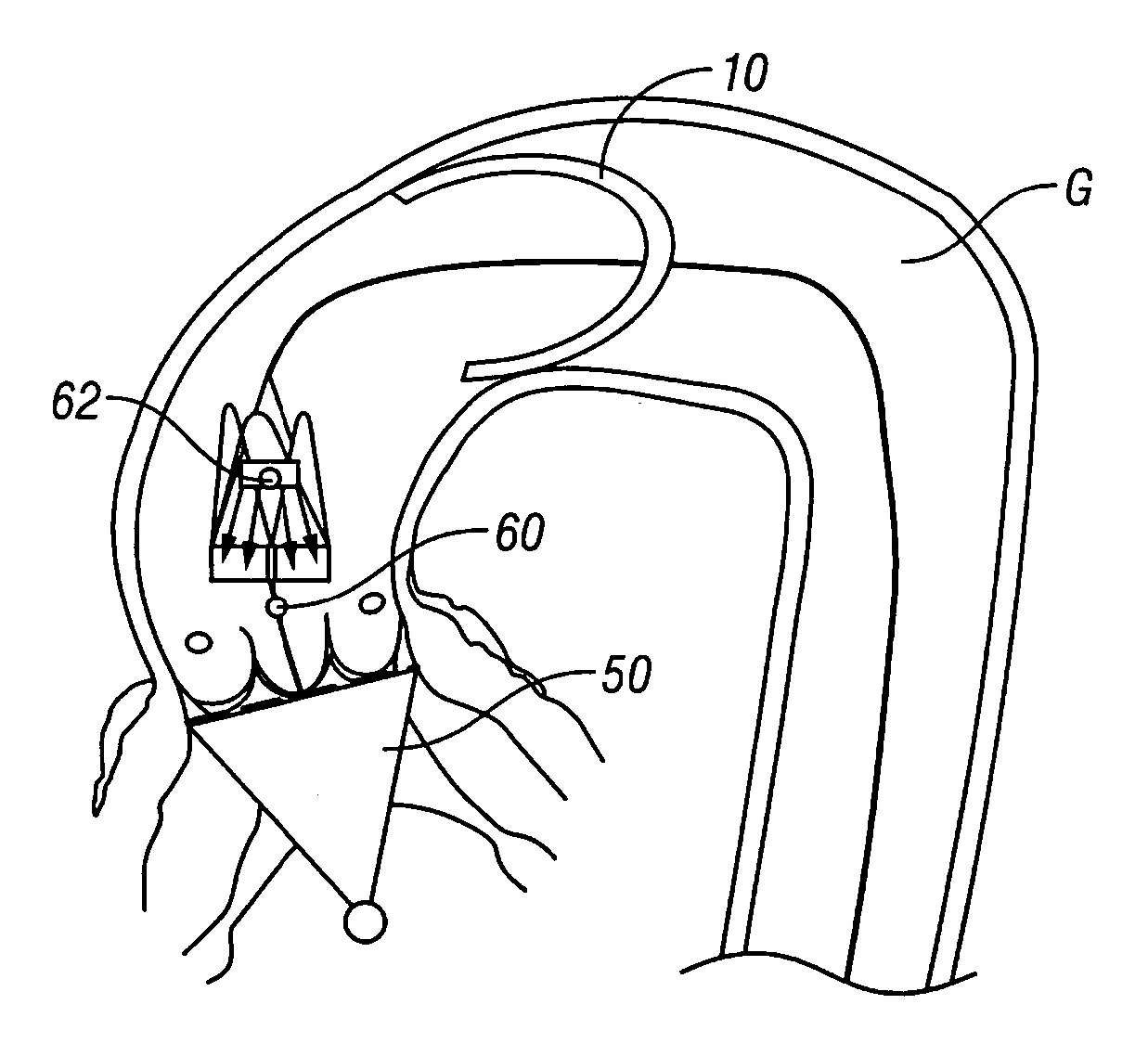
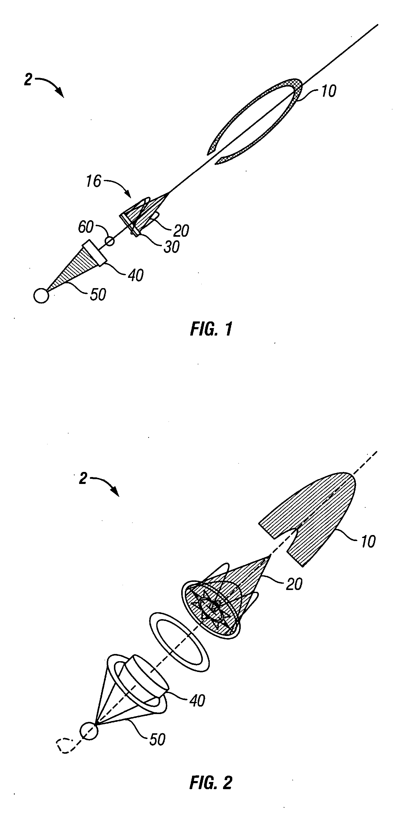
[0017]FIG. 1 shows a schematic of one embodiment of the present invention.

[0018]FIG. 2 shows an deployed configuration of the embodiment of FIG. 1.

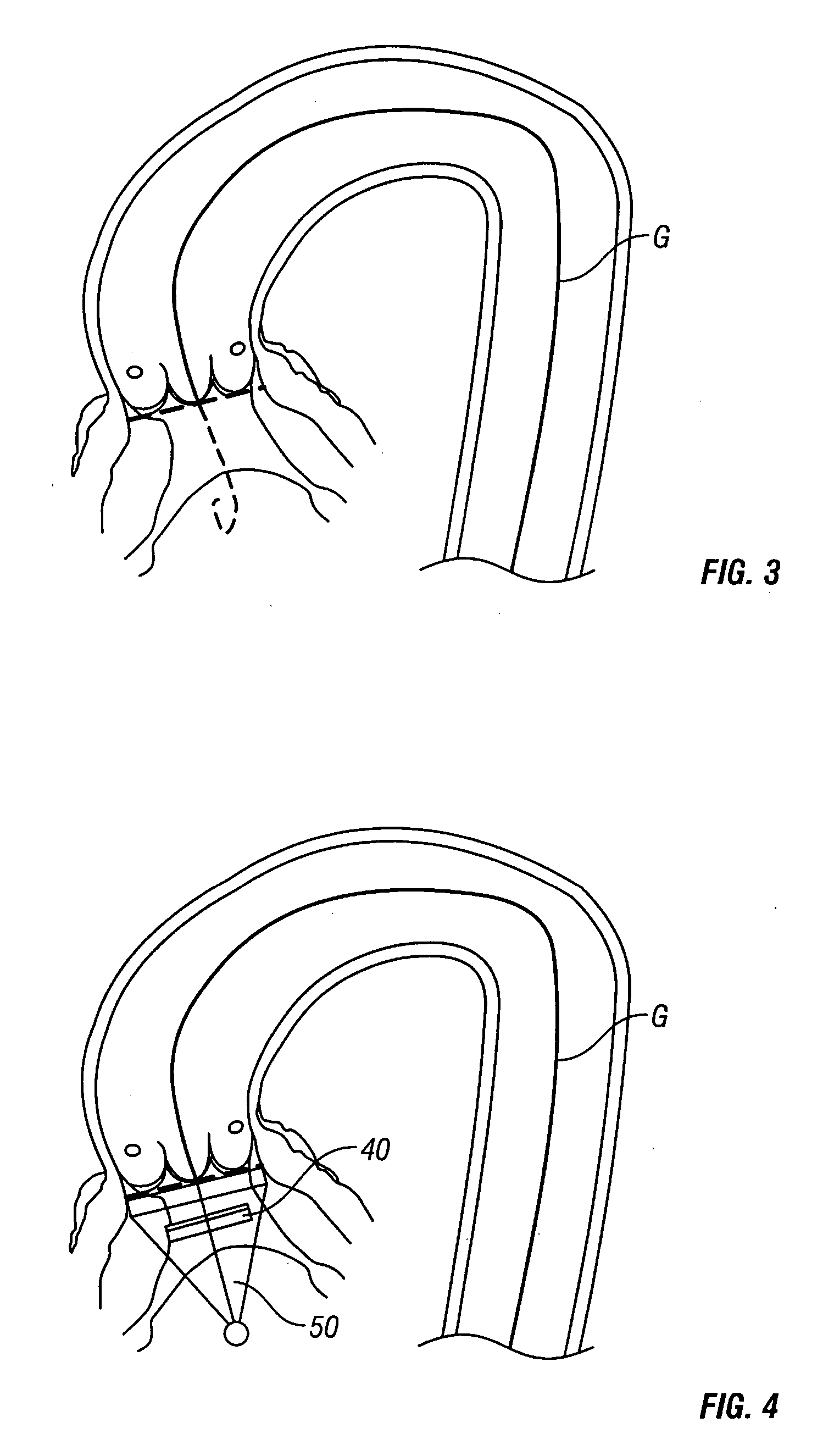
[0019]FIGS. 3 through 6 show one method of delivering various components of the present invention into the patient.

[0020]FIGS. 7 through 12 one method of delivering a valve prosthesis and the removal of tissue debris.

[0021]FIGS. 13 and 14 are schematics of a ring with fasteners according to the present invention.

[0022]FIGS. 15 through 18 show another embodiment of a ring with fasteners according to the present invention.

[0023]FIGS. 19 and 20 show an embodiment of a valve delivery assembly for use with one embodiment of a radial fastener delivery device.

[0024]FIGS. 21 through 23 are various views of a radial fastener delivery device.

[0025]FIGS. 24 through 26 show views of fasteners for use with a radial fastener delivery device.

[0026]FIG. 27 through 32 show the delivery of valve prosthesis using a radial fastener delivery device. ...


PUM


Abstract

Methods and apparatus are provided for valve repair or replacement. In one embodiment, the apparatus is a valve delivery device comprising a first apparatus and a second apparatus. The first apparatus includes a heart valve support having a proximal portion and a distal portion and a heart valve excisor slidably mounted on said first apparatus. The second apparatus includes a fastener assembly having a plurality of penetrating members mounted to extend outward when the assembly assumes an expanded configuration; and a heart valve prosthesis being releasably coupled to said second apparatus. The first apparatus and second apparatus are sized and configured for delivery to the heart through an opening formed in a femoral blood vessel. The heart valve prosthesis support is movable along a longitudinal axis of the device to engage tissue disposed between the anvil and the valve prosthesis. The system may include a tent and/or an embolic screen to capture debris from valve removal.

Description

[0001] The application claims the benefit of priority from copending U.S. Provisional Application Ser. No. 60 / 572,133 (Attorney Docket No. 40450-0006) filed May 17, 2004 and fully incorporated herein by reference for all purposes.BACKGROUND OF THE INVENTION [0002] 1. Technical Field [0003] The invention relates to apparatus and methods for minimally invasive heart valve replacement and is especially useful in aortic valve repair procedures. [0004] 2. Background Art [0005] Essential to normal heart function are four heart valves, which allow blood to pass through the four chambers of the heart in one direction. The valves have either two or three cusps, flaps, or leaflets, which comprise fibrous tissue that attaches to the walls of the heart. The cusps open when the blood flow is flowing correctly and then close to form a tight seal to prevent backflow. [0006] The four chambers are known as the right and left atria (upper chambers) and right and left ventricles (lower chambers). The ...

Claims


Application Information

Patent Timeline
Patent Type & Authority Applications(United States)
IPC IPC(8): A61F2/24A61B17/3205A61B17/12A61F2/01A61F2/02
CPCA61B17/068A61B17/320016A61F2/013A61F2/2409A61F2/2412A61F2/243A61F2220/0016
Inventor REALYVASQUEZ, FIDEL
Owner REALYVASQUEZ FIDEL
Why Eureka
Try Eureka