Slurry for slicing silicon ingot and method for slicing silicon ingot using same

a silicon ingot and slurry technology, applied in the direction of other chemical processes, manufacturing tools, chemistry apparatus and processes, etc., can solve the problems of reducing cutting efficiency, reducing feeding speed, and reducing cutting resistance during cutting processing of silicon ingots, so as to achieve efficient cutting and high quality

Inactive Publication Date: 2006-04-13
MITSUBISHI ELECTRIC CORP
View PDF3 Cites 31 Cited by
  • Summary
  • Abstract
  • Description
  • Claims
  • Application Information

AI Technical Summary

Benefits of technology

[0013] According to the present invention, a content of a basic material is at least 3.5% by mass with respect to the total mass of a liquid component of a slurry, organic amine is contained in a mass ratio of 0.5 to 5.0 with respect to water in a liquid component of the slurry, and pH of the slurry is 12 or more. Consequently, the cutting resistance during cutting processing of a silicon ingot is reduced, and a wafer of high quality can be obtained efficiently.

Problems solved by technology

However, when cutting processing is performed using such a cutting slurry for a long period of time, the viscosity of the slurry increases during the processing to increase the pulling resistance of a wire from a cut groove, which makes it necessary to decrease the feeding speed of the wire.
Accordingly, it is necessary to decrease the feeding speed (i.e., cutting speed) of a silicon ingot, which decreases a cutting efficiency.
Furthermore, the pulling resistance of the wire becomes excessive, which breaks the wire.
However, the breakage strength of the wire decreases accordingly, which makes it necessary to decrease the tension applied to the wire.
Therefore, when the tension of the wire is decreased, the cutting speed becomes low, and the displacement (deformation) of the wire becomes large.
Consequently, warping of a wafer, irregular thickness, and minute unevenness (saw mark) occur, resulting in a decrease in quality of a wafer.
When the feeding speed of the wire is increased to compensate for the delay of the cutting speed, thereby increasing the feeding speed of a silicon ingot, a margin with respect to dispersion failure of abrasive grains is lost at the cutting interface, with the result that the wire breaks due to the abrupt increase in tension.

Method used


Image

  • Slurry for slicing silicon ingot and method for slicing silicon ingot using same
  • Slurry for slicing silicon ingot and method for slicing silicon ingot using same
  • Slurry for slicing silicon ingot and method for slicing silicon ingot using same

Examples


example 1

[0056] 8 parts by mass of sodium hydroxide were dissolved in 100 parts by mass of water to obtain a basic aqueous solution. This aqueous solution, 100 parts by mass of triethanolamine, and 100 parts by mass of polyethylene glycol were mixed. To this mixed solution, 100 parts by mass of SiC abrasive grains (GC#1000, average particle diameter: about 10 μm, produced by Fujimi Inc.) were added, followed by stirring, whereby a slurry for cutting a silicon ingot was prepared. At this time, the mass ratio of triethanolamine with respect to water in a liquid component of the slurry was 100÷100=1.0. Furthermore, the pH of the obtained slurry at 25° C. was 13.3, and the initial viscosity thereof at 90° C. and a shear velocity of 57.6[s−1] was 50 mPa·s.

[0057] A polycrystalline silicon ingot sample (3 mm×3 mm×thickness: 1 mm) was polished under the following polishing conditions using the obtained slurry for cutting a silicon ingot. The slurry was collected every predetermined time (0, 2, 4, a...

example 2

[0066] A polycrystalline silicon ingot sample (3 mm×3 mm×thickness: 1 mm) was polished under the following polishing conditions, using the same slurry for cutting a silicon ingot as that in Example 1. A polished amount was obtained from the change in mass of the sample before and after polishing, and the polished amount was divided by a polishing time to obtain a polishing speed. Table 3 shows the results.

Polishing paddiameter 200 mm (produced by Buhler,polishing buffer, ultra-pad for 8-inch wafer)Sample position65 mm from the center of the padRotation number of200 rpmpolishing tablePolishing time5 minutesSlurry supply amount65 cc / minuteSlurry supply position65 mm from the center of the pad, backwardrotation by 30° of the sampleSlurry temperature80° C.Sample pressure10 N

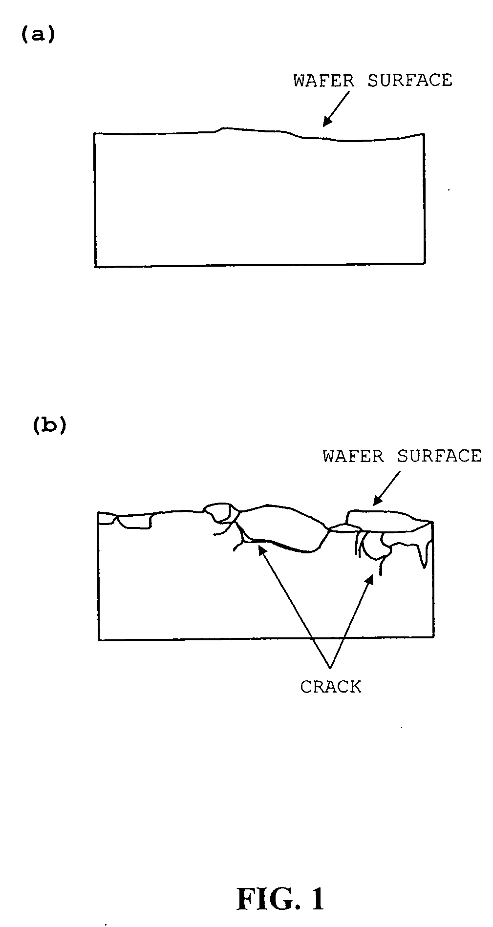
[0067] Next, the obtained wafer was washed with water, followed by drying. The polished surface of the ingot was observed with a microscope, and evaluated based on the following standard. Table 3 shows the results....

example 3

[0077] A slurry for cutting a silicon ingot containing 4.9% by mass of sodium hydroxide with respect to the total mass of a liquid component of a slurry, triethanolamine in a mass ratio of 0.5 with respect to water in the liquid component of the slurry, and 33% by mass of abrasive grains with respect to the total mass of the slurry was prepared, and the difference in cutting resistance caused by the difference in slurry temperature was investigated. The pH of the obtained slurry at 25° C. was 13.8.

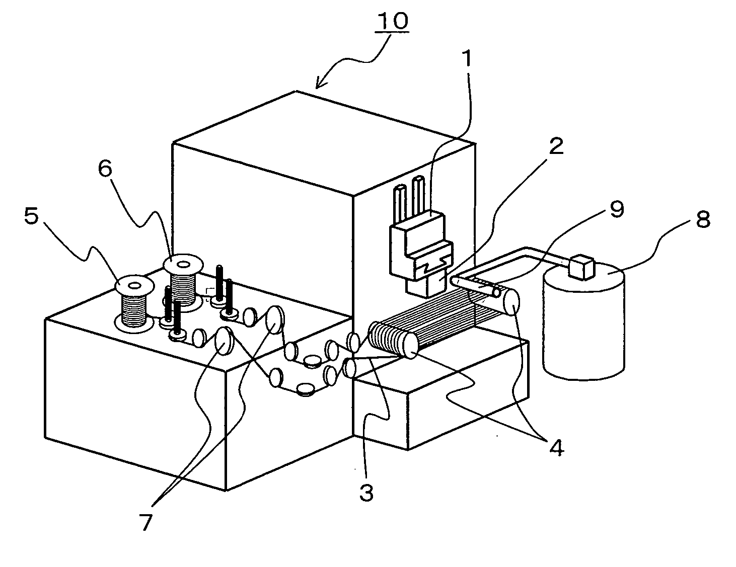
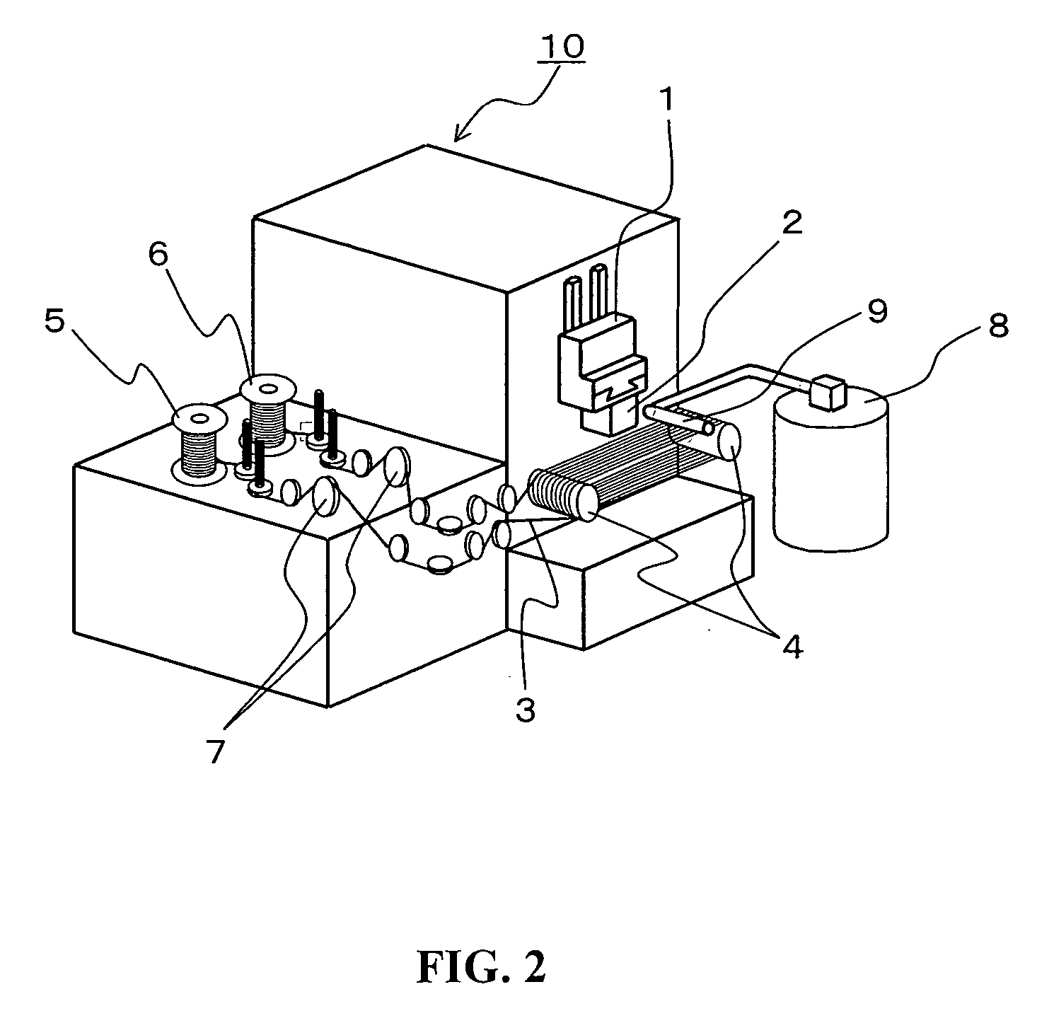
[0078] A polycrystalline silicon ingot (each side: 150 mm, length: 25 mm) was cut with a multi-wire saw in FIG. 2 under the following cutting conditions using the obtained slurry for cutting a silicon ingot and the deformation amount of the wire during processing was measured with an eddy-current displacement sensor.

Wire diameter100 μm (Type SRH, produced by JFE Steel)Wire pitch0.39 mmWire feeding speed600 m / minuteSilicon ingot feeding speed0.35 mm / minuteSlurry temperature25° C., 80° C....


PUM

PropertyMeasurementUnit
mass ratioaaaaaaaaaa
average grain diameteraaaaaaaaaa

Abstract

In a slurry for cutting a silicon ingot according to the present invention, a content of a basic material is at least 3.5% by mass with respect to the total mass of a liquid component of a slurry, organic amine is contained in a mass ratio of 0.5 to 5.0 with respect to water in a liquid component of the slurry, and pH of the slurry is 12 or more. Furthermore, according to a method of cutting a silicon ingot according to the present invention, the above-mentioned slurry for cutting a silicon ingot is used at 65° C. to 95° C. Consequently, the cutting resistance during cutting processing of a silicon ingot is reduced, and a wafer of high quality can be obtained efficiently.

Description

TECHNICAL FIELD [0001] The present invention relates to a slurry for cutting a silicon ingot used for cutting a single crystalline, polycrystalline, or amorphous silicon ingot to produce a wafer for a semiconductor or solar battery, and to a method of cutting a silicon ingot using the slurry. BACKGROUND ART [0002] Conventionally, cutting of a silicon ingot involves use of a wire saw, which is capable of cutting with a small cutting allowance and a uniform thickness, and capable of cutting a number of wafers at a time. Such cutting of a silicon ingot using a wire saw is performed by introducing a cutting slurry containing abrasive grains into a cutting interface while pressing a silicon ingot against a traveling wire. In such cutting of a silicon ingot using a wire, there is a demand for maintaining high wafer quality, enhancing a cutting speed, decreasing a cutting allowance or a cutting pitch, and reducing a wafer processing cost. [0003] In order to maintain high wafer quality, it ...

Claims


Application Information

Patent Timeline
Patent Type & Authority Applications(United States)
IPC IPC(8): B26D1/00C09K3/14B28D5/00
CPCB28D5/007C09K3/1463Y10T83/04Y02P70/10
Inventor TSURUTA, HIROZOHHAMAYASU, MASAYUKIKAWASAKI, TAKAFUMINISHIDA, HIROKAZUTOMINAGA, HISASHI
Owner MITSUBISHI ELECTRIC CORP
Why Eureka
Try Eureka