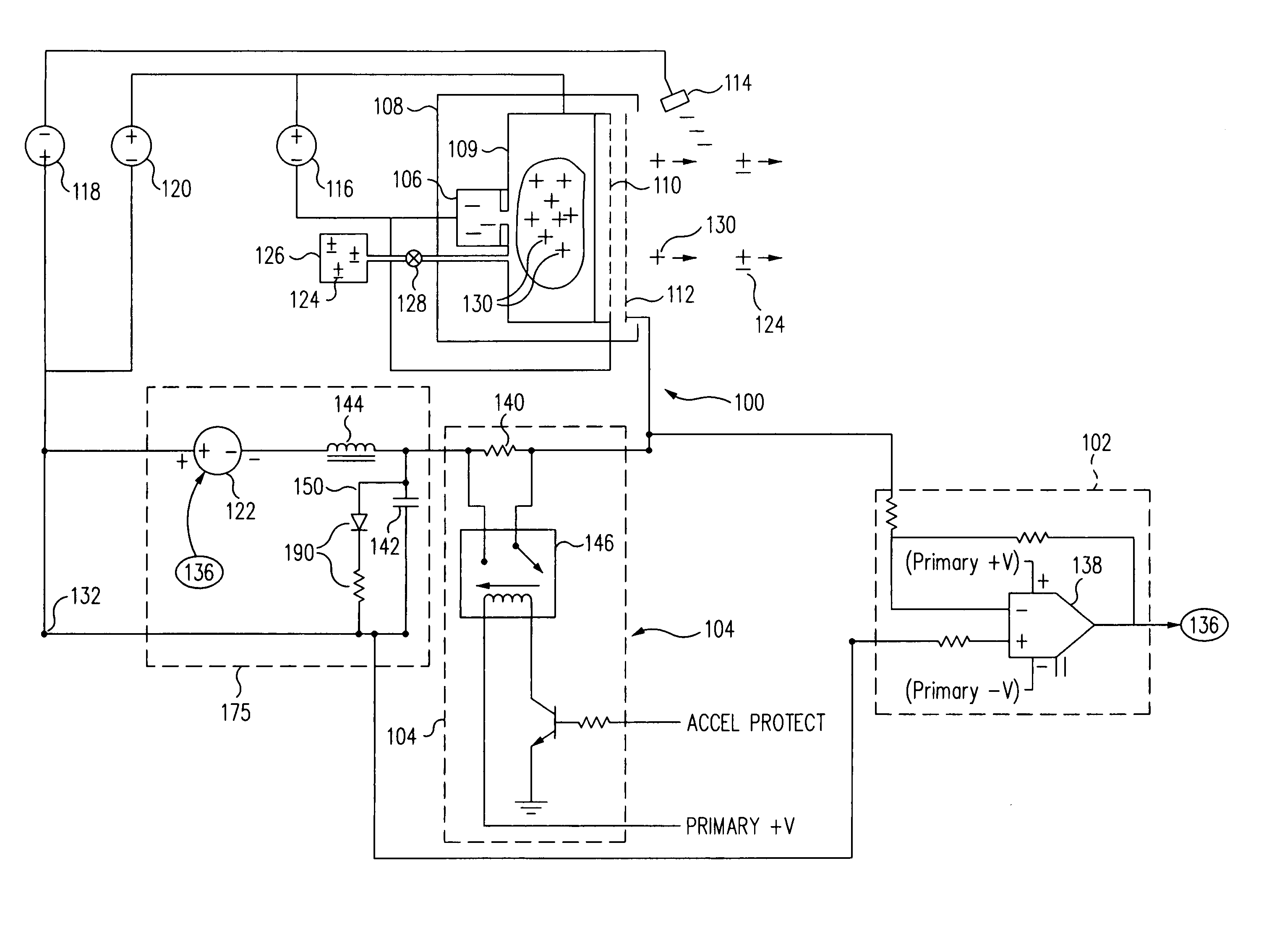
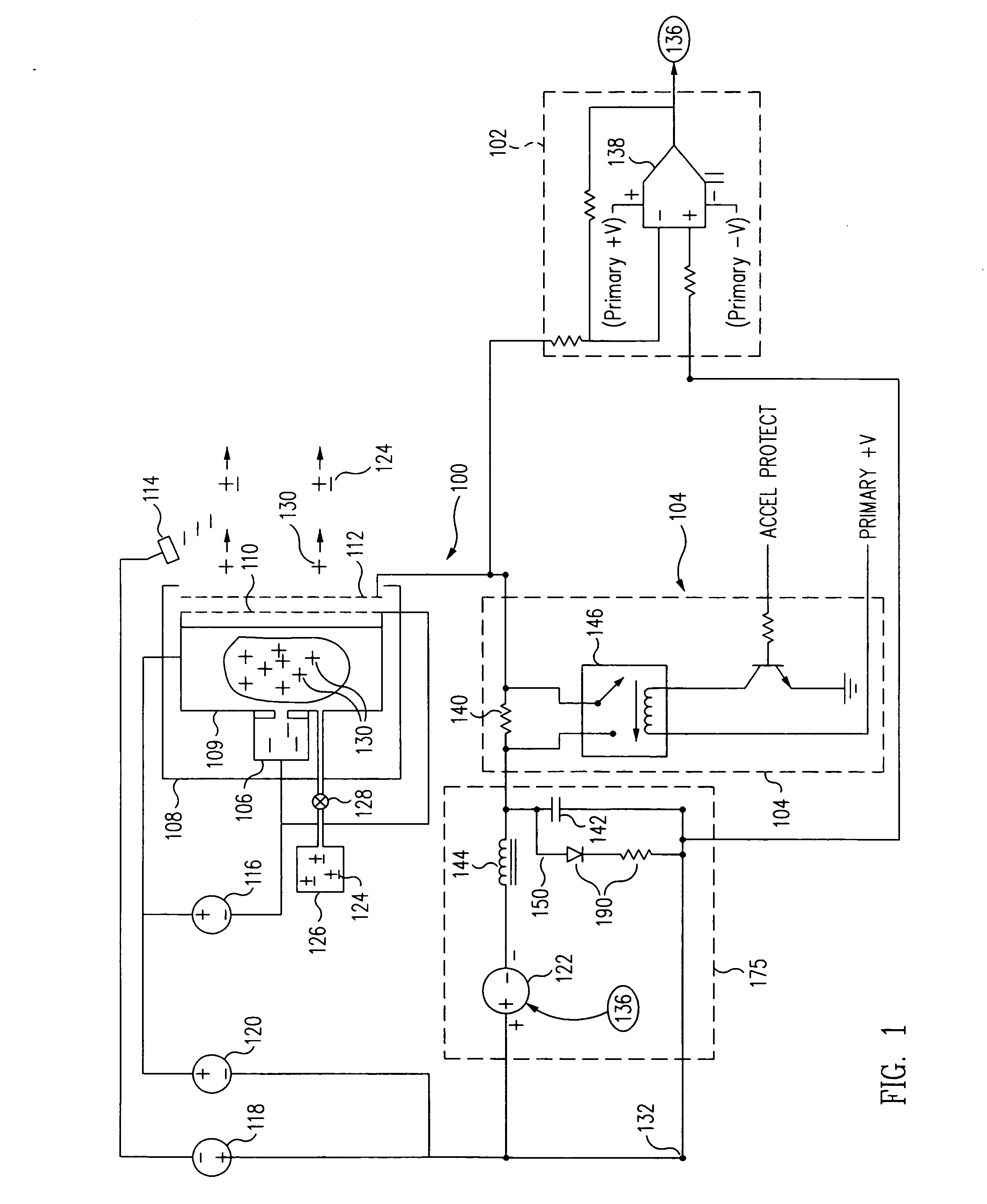
[0008] In accordance with the present invention, a circuit is provided that couples to the accelerator grid of an ion engine in such a way that the voltage differential, and hence, the energy contained in a plasma arc occurring between the screen grid and the accelerator grid of the engine, is minimized, thereby reducing or eliminating the damage to the grids caused by the arc.
[0009] In a first exemplary embodiment thereof, the novel grid arcing protection circuitry includes a protection circuit that comprises a fixed impedance in series between the accelerator grid and the output of the internal accelerator power source within the
ion thruster. During an arc between the accelerator grid and screen grid of the
ion thruster, the added impedance causes a rapid reduction in the voltage of the accelerator grid relative to that of the screen grid.
[0010] While it is desirable to have the added impedance present in the arc protection circuit during normal operation of the ion engine, it may be desirable to reduce its impedance during startup of the engine, so that the accelerator grid current can quickly achieve a relatively high startup level for a brief period of time required for the engine to start. For this purpose, the arcing protection circuit further includes a circuit for selectably
coupling the impedance into and out of the accelerator grid-to-accelerator-supply output path, and in one possible embodiment, this impedance
coupling circuit may comprise a simple
relay.
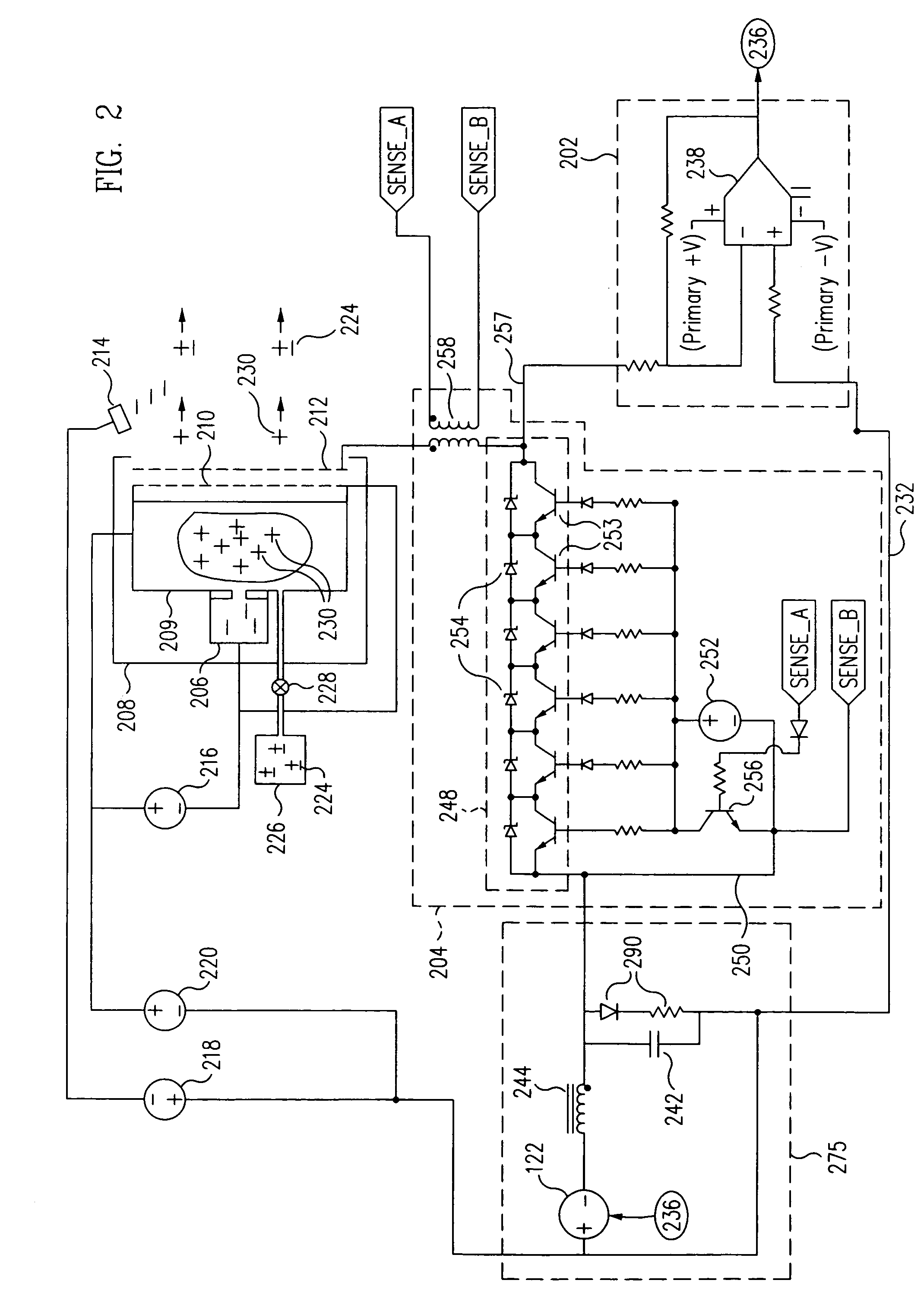
[0012] In an alternative exemplary embodiment, the grid arcing protection circuit can advantageously incorporate, in addition to the above accelerator grid monitoring circuit of the first embodiment, a variable impedance in place of the fixed impedance. As in the first embodiment, this impedance is coupled in series between the accelerator grid and the output of the internal accelerator power source within the ion thruster, the difference in this embodiment being that the impedance is variable. During a plasma arc between the screen and accelerator grids, the plasma arc causes the impedance of the circuit to increase rapidly. This action quickly reduces the relative voltage difference between the accelerator grid and the screen grid, thereby extinguishing or substantially limiting the energy of the arc almost instantaneously.
[0013] Advantageously, the accelerator
grid voltage is regulated at the required voltage by the accelerator grid monitoring circuit, while the variable impedance is in series with the accelerator grid, by an
error amplifier, which senses the voltage at the accelerator grid and provides a feedback
signal proportional to the accelerator
grid voltage that enables the magnitude of the internal accelerator power source within the ion thruster to be varied so as to maintain the accelerator grid at its required voltage during normal operation.
[0014] In one advantageous embodiment thereof, the variable impedance comprises an electrically actuated switch. The
active switch may comprise a plurality of first transistors, which may be MOSFETs or Bipolar Junction Transistors, (“BJTs”), coupled in series between the accelerator grid and the output of the internal accelerator power source within the ion thruster. These transistors have their respective bases coupled in parallel and biased such that they operate in the fully saturated mode during normal thruster operation. A second
transistor is coupled between the bases of the first
transistor and the output of the internal accelerator power source within the ion thruster. A
pulse transformer is also included, which has a primary winding coupled in series between the accelerator grid and the collector of the first
transistor in the variable impedance string of transistors. The excess current during a plasma arc is sensed by the
pulse transformer, with the secondary of the
pulse transformer connected directly to the second transistor and a base circuit of the second transistor. The second transistor is coupled between the bases of the first transistors in the variable impedance string, which is connected to the internal accelerator power source within the ion thruster; the action of the pulse
transformer being used to turn off all of the transistors in the variable impedance string rapidly. This action quickly reduces the voltage difference between the accelerator grid relative to the screen grid, thereby almost instantaneously extinguishing or substantially limiting the energy of the arc.

