Exhaust gas scrubber for epitaxial wafer manufacturing device

a technology of epitaxial wafers and scrubbers, which is applied in the direction of combustion air/fuel air treatment, carburetor air, and separation processes, etc. it can solve the problems of affecting the productivity affecting the efficiency of purifying the exhaust gas and clogging the nozzle, and affecting the efficiency of the epitaxial wafer manufacturing device, so as to prevent the variation in the mutual installation spacing of the two, prevent the reduction of the reduction

Active Publication Date: 2006-04-13
SUMCO CORP
View PDF0 Cites 4 Cited by
  • Summary
  • Abstract
  • Description
  • Claims
  • Application Information

AI Technical Summary

Benefits of technology

[0015] Joints may be further formed in the outer tube, the middle tube and the inner tube configuring the wash tube unit so as to prevent variation in their mutual installation spacing. Also, the wash tube unit may spray the wash water toward the interior of the scrubber inlet tube at an angular range of 15 to 25° relative to a longitudinal direction thereof.
[0016] According to the exhaust gas scrubber for an epitaxial wafer manufacturing device of the present invention, deposits accumulated in the scrubber inlet tube are removed by spraying the inert gas and wash water towards an inner wall of the scrubber inlet tube from the triple-structured wash tube unit. By removing the deposits of exhaust gas components from the epitaxial wafer manufacturing device, in the scrubber inlet tube of the exhaust gas scrubber, reductions in exhaust-gas purifying performance caused by excessive accumulation of deposits can be prevented.
[0017] Furthermore, by automatically and regularly conducting this cleaning of the scrubber inlet tube at a timing different from the epitaxial growth process, it is possible to remove the deposits safely without reduction in the productivity of the epitaxial wafer manufacturing device.

Problems solved by technology

This type of chlorine exhaust gas is strongly corrosive, and cannot be released into an atmosphere directly.
When such a product is left to accumulate, it causes a degradation in efficiency for purifying the exhaust gas and a clogging of the nozzle or the like which sprays the exhaust gas.
However, in the aforementioned method for purifying an exhaust gas and a device therefor disclosed in Patent Document 1 and 2, the deposits (product) produced inside the tube are mechanically removed by a manual operation, and time is required for this removal, during which the manufacturing device including an exhaust gas device must be stopped, thereby productivity is impeded.
Moreover, since these are methods for removing the deposits by a manual operation, in the case in which an amount of deposits is large, much labor is required and it may be impossible to completely remove the deposits.
Furthermore, in the case in which, for example, the exhaust gas components react with the wash water to produce combustible deposits or the like, removal of the deposits by a manual operation involves serious concerns from the safety standpoint.
Moreover, it is necessary to conduct cleaning at a frequency of once every 2 or 3 days for the purposes of removing deposits from the exhaust gas scrubber, and on each occasion, the epitaxial wafer manufacturing device and the exhaust gas scrubber must be stopped to conduct the work of cleaning, which constitutes a factor reducing an operating efficiency of the device, and thus reducing productivity.

Method used


Image

  • Exhaust gas scrubber for epitaxial wafer manufacturing device
  • Exhaust gas scrubber for epitaxial wafer manufacturing device
  • Exhaust gas scrubber for epitaxial wafer manufacturing device

Examples


example

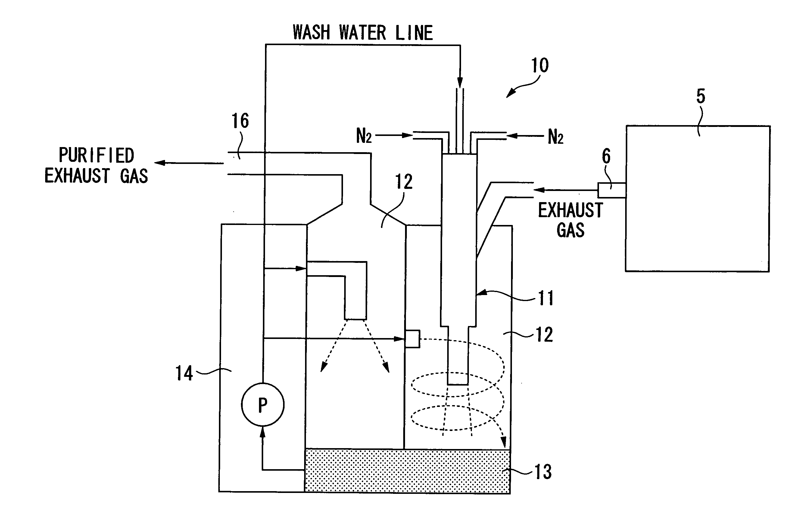
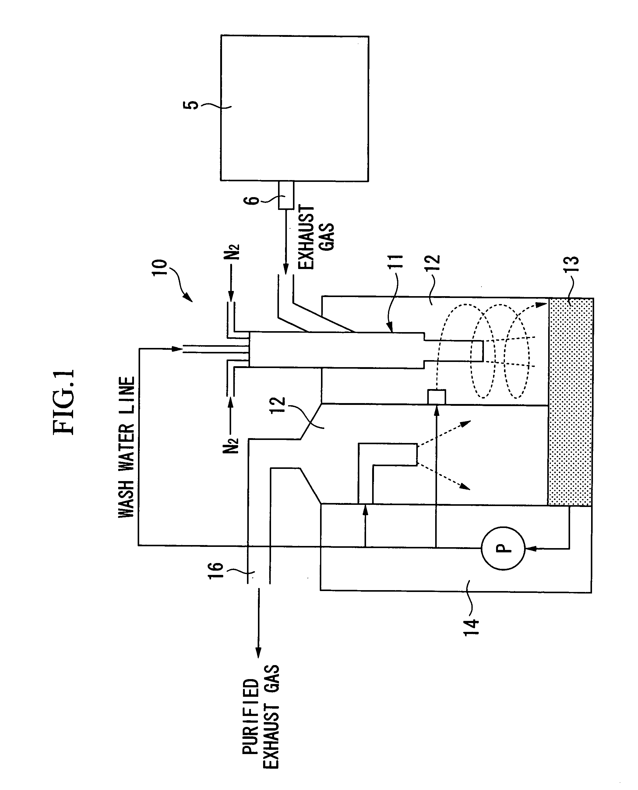
[0046] The inventors of the present invention verified changes in a suction pressure with time which increase as deposits increase in the scrubber inlet tube of the exhaust gas scrubber of the present invention. With regard to the verification, the exhaust gas scrubber of the present invention having cleaning functions as in the above-described embodiment, and a conventional exhaust gas scrubber without the cleaning functions for this scrubber inlet tube were used, a prescribed amount of exhaust gas was made to continuously flow through each of the exhaust gas scrubbers, and variations in the suction pressure were measured.

[0047] Regarding results of this verification, a comparative example using the conventional exhaust gas scrubber is shown in FIG. 7, and an example of the present invention using the exhaust gas scrubber of the present invention is shown in FIG. 8. According to FIG. 7 and FIG. 8, in the exhaust gas scrubber of the comparative example, a range of variation in the ...


PUM

PropertyMeasurementUnit
bore diameteraaaaaaaaaa
angleaaaaaaaaaa
bore diameteraaaaaaaaaa

Abstract

This exhaust gas scrubber for an epitaxial wafer manufacturing device includes: a scrubber inlet tube for introducing an exhaust gas discharged from an epitaxial wafer manufacturing device; and a wash tube unit formed inside the scrubber inlet tube for spraying wash water toward an interior of the scrubber inlet tube from one end thereof so as to wash adhesions inside the scrubber inlet tube, wherein the wash tube unit includes an outer tube through which inert gas constantly flows, a middle tube which is formed inside the outer tube and through which inert gas intermittently flows, and an inner tube which is formed inside the middle tube and through which the wash water and inert gas alternately flow.

Description

BACKGROUND OF THE INVENTION [0001] 1. Field of the Invention [0002] This invention relates to an exhaust gas scrubber for an epitaxial wafer manufacturing device which captures and separates exhaust gas components produced by an epitaxial wafer manufacturing device so as to purify an exhaust gas. [0003] This application claims priority from Japanese Patent Application No. 2004-297531 filed on Oct. 12, 2004, the content of which is incorporated herein by reference. [0004] 2. Background Art [0005] A device for manufacturing silicon epitaxial wafers which are used as substrates for semiconductor devices and the like produces chlorine exhaust gas including SiHCl3 gas necessary for epitaxial growth. [0006] This type of chlorine exhaust gas is strongly corrosive, and cannot be released into an atmosphere directly. Therefore, SiHCl3 components in the exhaust gas are captured by an exhaust gas scrubber so as to purify the exhaust gas, and then the exhaust gas is released. [0007] This exhaus...

Claims


Application Information

Patent Timeline
Patent Type & Authority Applications(United States)
IPC IPC(8): B01D47/00
CPCB01D47/06B01D53/18B01D53/78Y10S261/54
Inventor RIKIHISA, YASUHIRO
Owner SUMCO CORP
Why Eureka
Try Eureka