
Magnetic-field concentration in inductively coupled plasma reactors

a plasma reactor and inductively coupled technology, applied in the direction of furnaces without endless cores, chemical vapor deposition coatings, coatings, etc., can solve the problems of difficult to completely fill high-aspect-ratio gaps using conventional cvd techniques, limited plasma-reactor densities, and poor gapfill ability. achieve the effect of increasing plasma density and improving plasma uniformity

Inactive Publication Date: 2006-04-13
APPLIED MATERIALS INC
View PDF8 Cites 37 Cited by
  • Summary
  • Abstract
  • Description
  • Claims
  • Application Information

AI Technical Summary

Benefits of technology

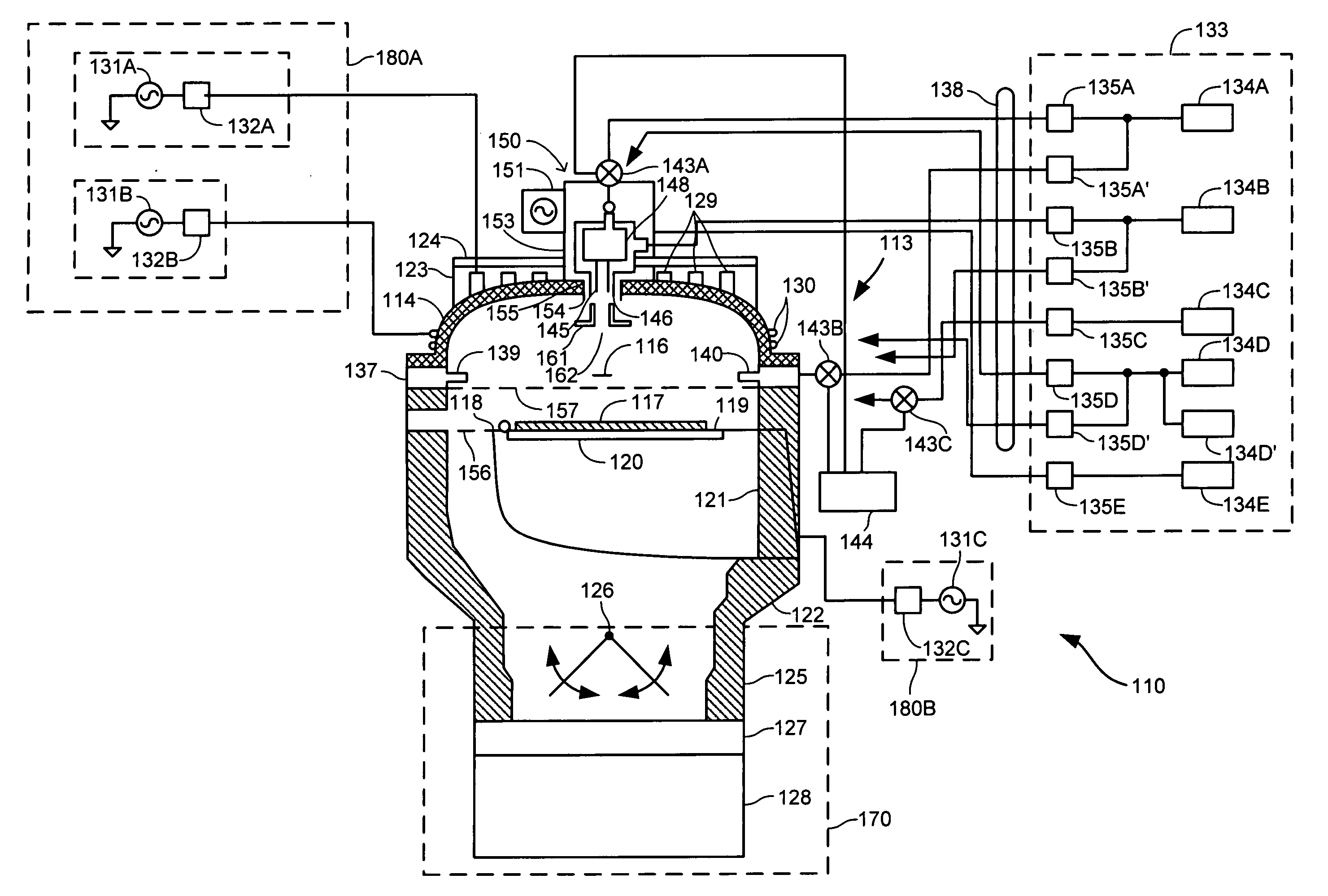
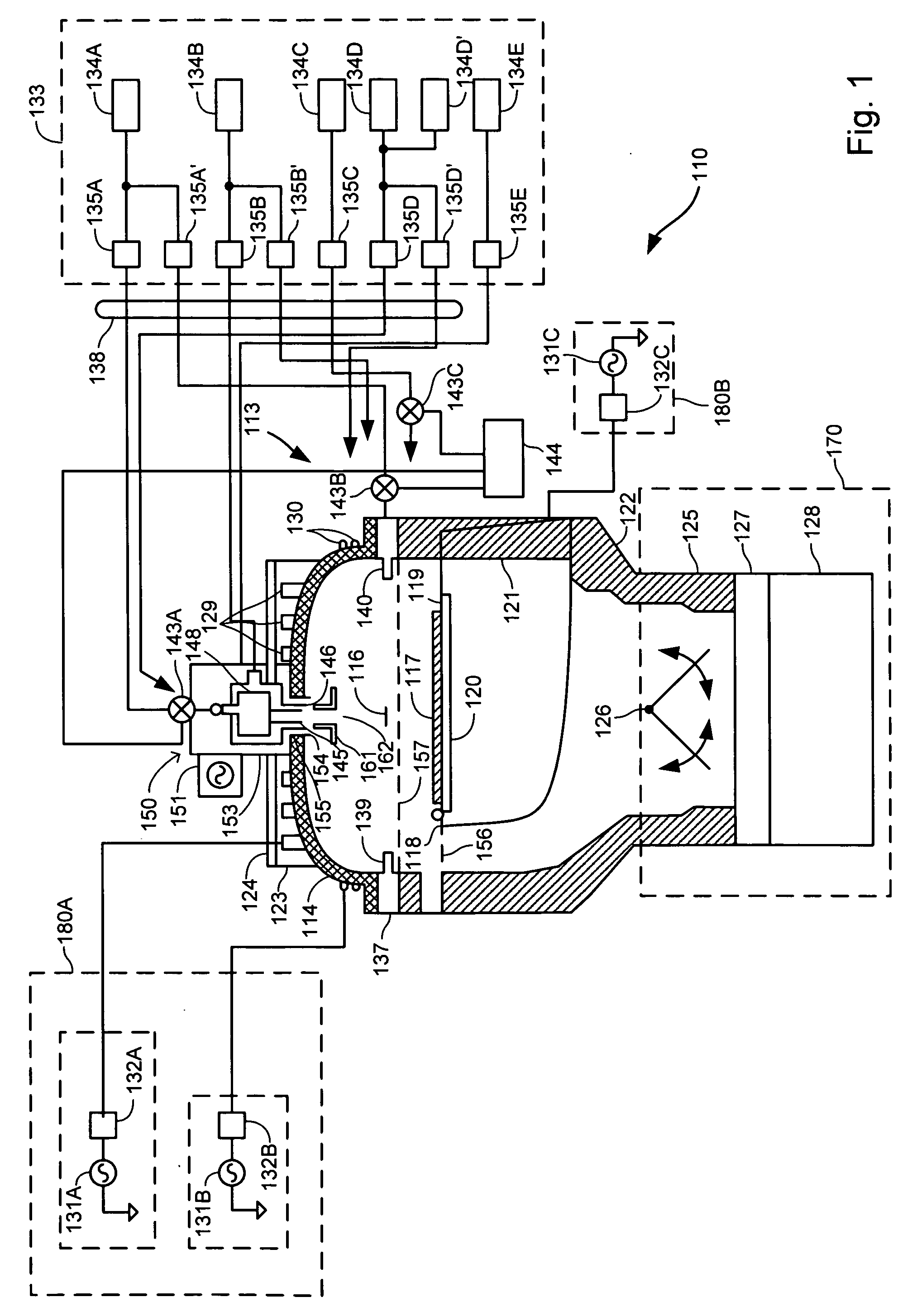
[0007] Embodiments of the invention provide methods and systems that include a magneto-dielectric material as part of an RF coil assembly in an ICP reactor to concentrate magnetic fields generated by the RF coil. This may permit both the plasma density to be increased and for the plasma uniformity to be improved.

Problems solved by technology

One persistent challenge faced by semiconductor manufacturers in the design and fabrication of such densely packed integrated circuits is the desire to prevent spurious interactions between circuit elements, a goal that has required ongoing innovation as geometry scales continue to decrease.
High-aspect-ratio gaps are difficult to fill completely using conventional CVD techniques, which tend to have relatively poor gapfill abilities.
It is generally desirable to increase the plasma density to improve the characteristics of a number of deposition processes, including gapfill processes in particular, but there are practical limits to densities that may be achieved with current plasma-reactor designs.
Such an approach has a number of adverse effects that are a consequence of resulting increasing in heat losses.
As temperatures rise because of the increased power, there is a greater risk of parts in the reactor burning out.
In addition, the excess heat affects ceramic parts that are commonly included in such reactors, resulting in the generation of more particulates that flake from the ceramic parts and that consequently contaminate the film being deposited.

Method used


Image

  • Magnetic-field concentration in inductively coupled plasma reactors
  • Magnetic-field concentration in inductively coupled plasma reactors
  • Magnetic-field concentration in inductively coupled plasma reactors

Examples


Embodiment Construction

[0020] Embodiments of the invention provide an ICP reactor that includes magnetic-field concentrators as part of coil assemblies used for inductive coupling of power into plasmas formed within a chamber of the ICP reactor. In certain embodiments, the magnetic-field concentrators comprise a magneto-dielectric material, which acts to lower the effective electric conductivity and increase the effective magnetic conductivity while maintaining relatively high thermal conductivity of the coil assemblies. The effect of such a combination is to concentrate the magnetic field generated by the inductive coils substantially without the production of eddy currents, which in turn permits the formation of denser plasmas without significant temperature changes.

[0021] These effects are due in part to the dielectric characteristics of the magneto-dielectric material. For example, while the magnetic field could be concentrated by use of a metallic material, such a material would not act to effective...


PUM

PropertyMeasurementUnit
Electrical resistivityaaaaaaaaaa
Dielectric polarization enthalpyaaaaaaaaaa

Abstract

A substrate processing system is provided with a housing defining a process chamber. A substrate holder is disposed within the process chamber and configured to support a substrate during substrate processing. A gas delivery system is configured to introduce a gas into the process chamber. A pressure-control system is provided for maintaining a selected pressure within the process chamber. A high-density-plasma generating system is operatively coupled with the process chamber and includes a coil for inductively coupling energy into a plasma formed within the process chamber. It also includes magneto-dielectric material proximate the coil for concentrating a magnetic field generated by the coil. A controller is also provided for controlling the gas-delivery system, the pressure-control system, and the high-density-plasma generating system.

Description

BACKGROUND OF THE INVENTION [0001] One of the primary steps in the fabrication of modern semiconductor devices is the formation of a film, such as a silicon oxide film, on a semiconductor substrate. Silicon oxide is widely used as an insulating layer in the manufacture of semiconductor devices. As is well known, a silicon oxide film can be deposited by a thermal chemical-vapor deposition (“CVD”) process or by a plasma-enhanced chemical-vapor deposition (“PECVD”) process. In a conventional thermal CVD process, reactive gases are supplied to a surface of the substrate, where heat-induced chemical reactions take place to produce a desired film. In a conventional plasma-deposition process, a controlled plasma is formed to decompose and / or energize reactive species to produce the desired film. [0002] Semiconductor device geometries have decreased significantly in size since such devices were first introduced several decades ago, and continue to be reduced in size. This continuing reducti...

Claims


Application Information

Patent Timeline
IPC IPC(8): H01L21/20C23C16/00
CPCC23C16/045C23C16/401C23C16/507H01J37/321H05B6/26
Inventor LU, SIQINGLAI, CANFENGLIANG, QIWEILONG, MAOLINCHOU, IRENEBLOKING, JASONKIM, STEVEN H.YIEH, ELLIE Y.
Owner APPLIED MATERIALS INC
Learn More