Adaptive interface using flexible fingers

a flexible finger and adaptive technology, applied in the direction of cooling/ventilation/heating modification, semiconductor/solid-state device details, semiconductor devices, etc., can solve the problems of large stress induced during the temperature cycle of manufacture and operation, and the special properties of the layer chosen for its special properties may not be ideally suited for direct lamination, cracking or delamination, etc., to achieve the effect of easing mechanical and/or thermal stress

Inactive Publication Date: 2006-04-13
PETER C SALMON LLC A CALIFORNIA LIMITED LIABILITY
View PDF12 Cites 27 Cited by
  • Summary
  • Abstract
  • Description
  • Claims
  • Application Information

AI Technical Summary

Benefits of technology

[0013] The current invention is an Interface Adaptor that includes a base layer and flexible fingers extending from the base layer. It is typically interposed between two objects to ease mechanical and / or thermal stresses that would otherwise occur at the joint. It may also be used as a shock absorber.

Problems solved by technology

As a practical matter, layers chosen for their special properties may not be ideally suited for direct lamination.
They may have dissimilar expansion characteristics for example, which could lead to cracking or de-lamination when the overall component is subjected to temperature changes.
), while silicon has a CTE of approximately 3 ppm / ° C. This means that if an integrated circuit (IC) chip is directly attached to a copper member, large stresses will be induced during the temperature cycles of manufacture and operation.
These stresses may cause cracking / failure of the chips, performance degradation, or de-lamination.
Larger chips require an epoxy glue layer to hold things together and prevent cracking, and the glue layer creates problems in rework.
Usually rework is not attempted if an epoxy under layer has been used, and this can lead to high reject costs.
The complex components may include arbitrary angles that would be difficult to manufacture using other existing fabrication methods such as stamping, milling, or drilling.

Method used


Image

  • Adaptive interface using flexible fingers
  • Adaptive interface using flexible fingers
  • Adaptive interface using flexible fingers

Examples


Embodiment Construction

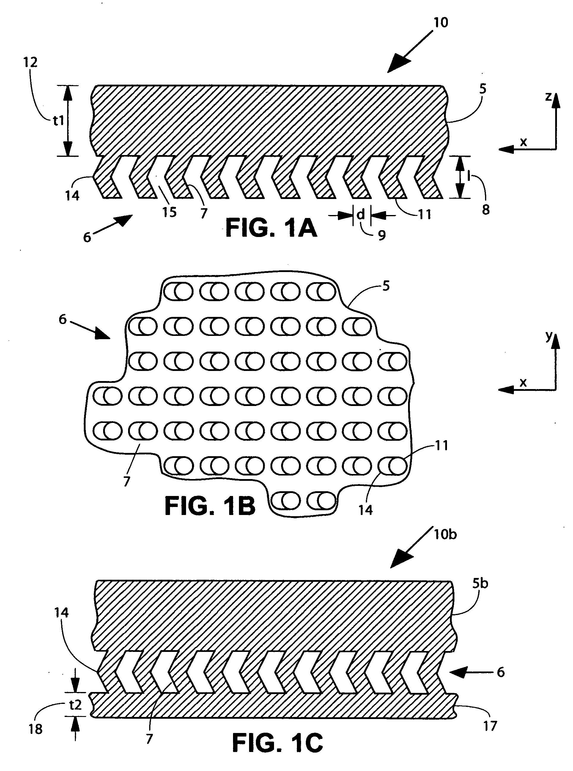
[0029]FIG. 1A shows a fragment of an Interface Adaptor 10 of the current invention in cross-section, including a base layer 5 and an array 6 of fingers 7. By virtue of its length, 1, 8 and its diameter, d, 9, each finger 7 has flexibility that allows its end 11 to move in the −x and −y directions relative to base layer 5. Base layer 5 is preferably a planar element defined in the −x and −y directions, and having a thickness, t1, t2. Each finger 7 also preferably has a bend 14 in it, providing flexibility in the −z direction, normal to base layer 5. The bend in each finger enables it to operate like a spring, particularly with regard to expansion / contraction in the −z direction. Because of gaps 15 between fingers 7, each finger can move independently of its neighbors. The fact that each finger acts flexibly and independently enables a collective behavior for the array 6 of fingers, wherein localized stresses between Interface Adaptor 10 and an attached object or component can be reli...


PUM


Abstract

A multi-function interface adaptor comprises a base layer and flexible fingers extending from it. The interface adaptor is interposed between two objects to provide a mechanical and/or thermal interface with stress relief or shock absorption. Using bent fingers operating like springs, shocks and distributed stresses can be relieved in the plane of the adaptor, as well as normal to the plane. A preferred embodiment is an Interface Adaptor that replaces thermal grease between a semiconductor chip and its associated heat sink.

Description

RELATED APPLICATIONS [0001] This application claims priority to Provisional Application Ser. No. 60 / 617,727 filed Oct. 12, 2004.THE INVENTION [0002] This invention relates to interfaces between components having dissimilar thermal or mechanical properties, and more particularly to multi-function adaptive interfaces that efficiently dissipate heat and relieve thermal and mechanical stresses between bonded components. BACKGROUND OF THE INVENTION [0003] The process of fabricating or assembling complex components by laminating multiple layers is well known. Each layer may contribute different properties or benefits to the whole: these may include structural strength, electrical conductivity, thermal conductivity, stress relief, shock absorption, planarization, dielectric properties, and sensing properties such as found in thermocouple sensors and strain sensors. [0004] As a practical matter, layers chosen for their special properties may not be ideally suited for direct lamination. They...

Claims


Application Information

Patent Timeline
Patent Type & Authority Applications(United States)
IPC IPC(8): H05K7/20
CPCH01L21/4871H01L23/433H01L2924/3011H01L2924/0002H01L2924/00
Inventor SALMON, PETER C.
Owner PETER C SALMON LLC A CALIFORNIA LIMITED LIABILITY
Why Eureka
Try Eureka