
Method of manufacturing carbon nanotube field emission device

a carbon nanotube and emission device technology, applied in the field of carbon nanotube field emission device manufacturing, can solve the problems of reducing the work function, limiting the life span of such a micro tip, and not being able to achieve cvd at a low temperatur

Inactive Publication Date: 2006-04-13
SAMSUNG SDI CO LTD
View PDF21 Cites 6 Cited by
  • Summary
  • Abstract
  • Description
  • Claims
  • Application Information

AI Technical Summary

Benefits of technology

[0012] It is therefore an object of the present invention to provide an improved method of manufacturing a carbon nanotube emitter and a a carbon nanotube field emission device.
[0014] It is also an object of the present invention to provide carbon nanotube emitters with a simple manufacturing process and being capable of thermally protecting other components including a substrate, and a method of manufacturing a device using the same.
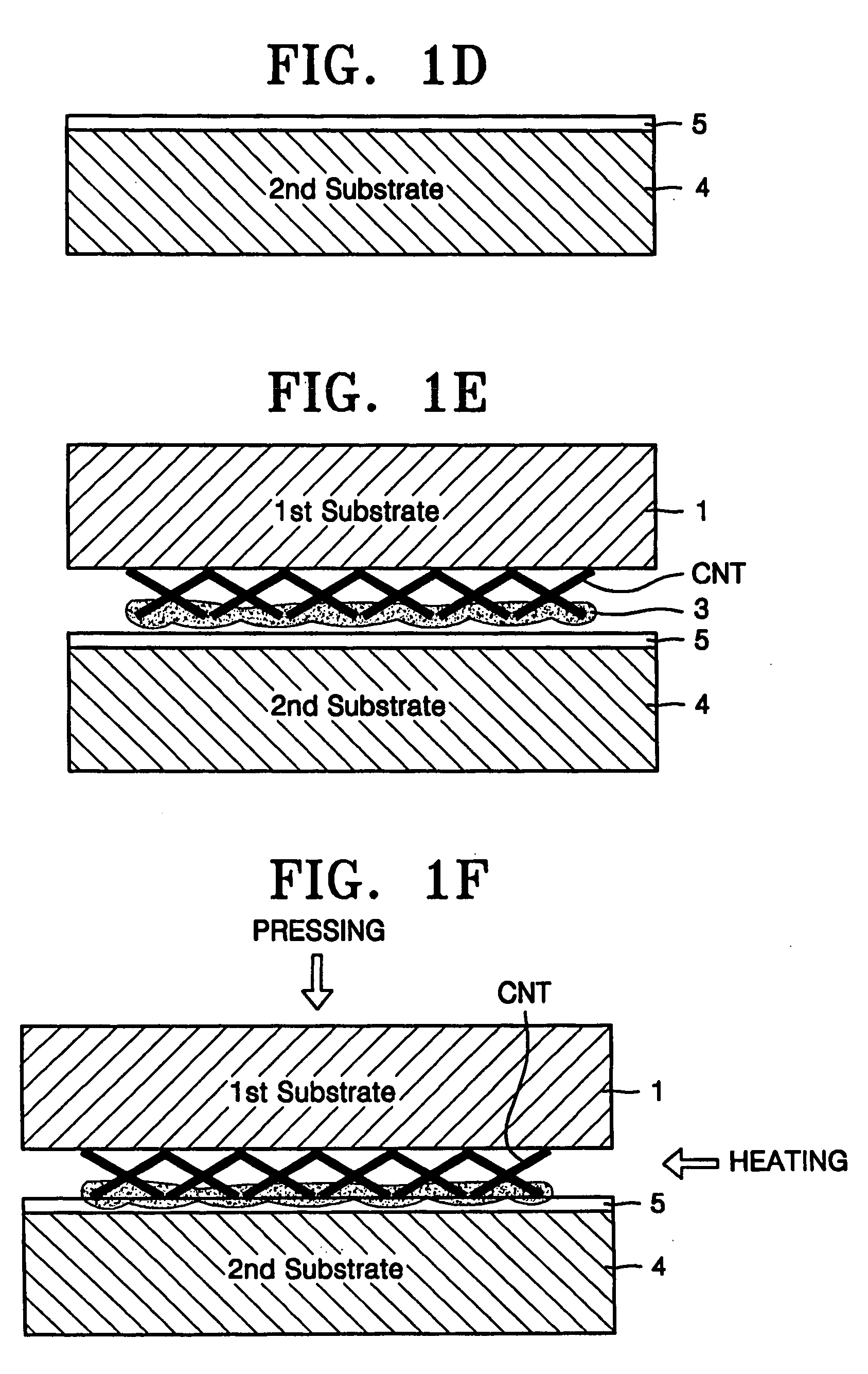
[0021] In the bonding, the second metal layer is heated together with the second substrate to a predetermined temperature to perform hot pressure bonding. As a result, carbon nanotubes can be efficiently bonded to the second substrate.

Problems solved by technology

However, the life span of such a micro tip is shortened due to effects of an atmospheric gas, a non-uniform electric field, and the like.
However, there is a limit to reducing the work function.
Therefore, CVD at a low temperature is not preferable.
Furthermore, CVD equipment used for obtaining highly pure carbon nanotubes is high-priced, and thus CVD has a high manufacturing cost.
Since the carbon nanotube paste includes various kinds of organic and inorganic solvents, it is difficult to obtain highly pure carbon nanotube electron emitters.

Method used


Image

  • Method of manufacturing carbon nanotube field emission device
  • Method of manufacturing carbon nanotube field emission device
  • Method of manufacturing carbon nanotube field emission device

Examples


Embodiment Construction

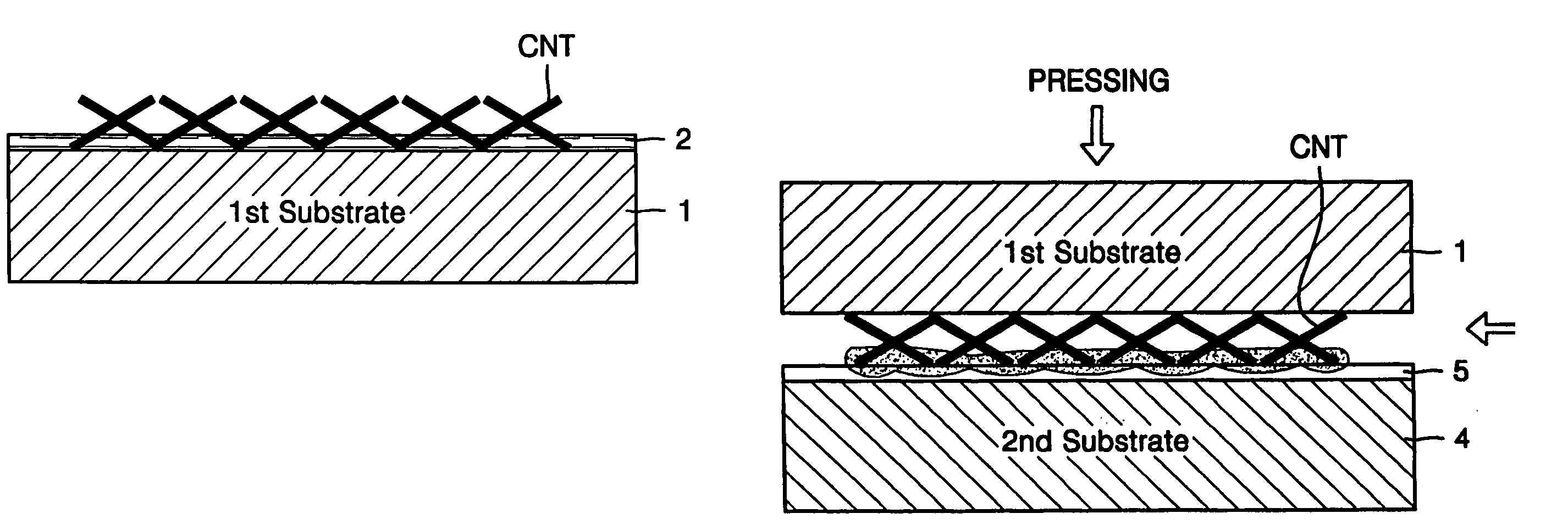
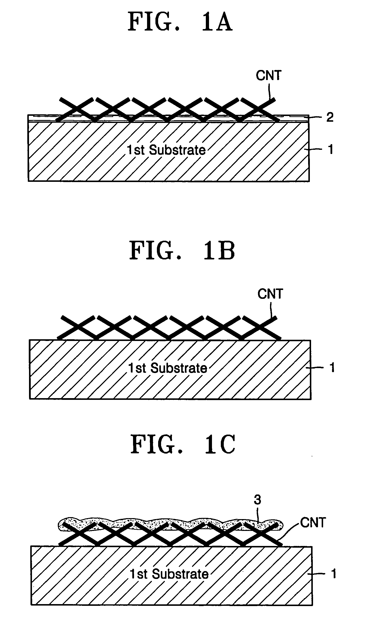
[0032] Hereinafter, a method of manufacturing a carbon nanotube emitter and a method of manufacturing a field emission device adopting the carbon nanotube emitter according to embodiments of the present invention will be described in detail with reference to the attached drawings. In the drawings, a field emission device including carbon nanotubes is exaggerated for clarity. In particular, one element may be illustrated larger than other elements when necessary and may be omitted to more clearly describe the embodiment.

[0033]FIGS. 1A through 1I illustrate a method of manufacturing a carbon nanotube emitter, according to an embodiment of the present invention.

[0034] As shown in FIG. 1A, carbon nanotube powder is mixed with an organic dispersing agent, for example, ethanol, or an inorganic dispersing agent, for example, water 2. Next, the mixture is coated on the surface of a first substrate 1 formed of Si or sodalime glass.

[0035] As shown in FIG. 1B, the dispersing agent 2 is remo...


PUM


Abstract

A carbon nanotube emitter and a method of manufacturing a carbon nanotube field emission device using the carbon nanotube emitter. Powdered carbon nanotubes are adsorbed onto a first substrate. A metal is deposited on the carbon nanotubes. The resultant structure is pressure-bonded to a surface of a cathode. The first substrate is spaced apart from a second substrate to tense the carbon nanotubes, so that the carbon nanotubes are perpendicular to the first substrate.

Description

CLAIM OF PRIORITY [0001] This application claims the priority of Korean Patent Application No. 10-2004-0031670, filed on May 6, 2004, in the Korean Intellectual Property Office, the disclosure of which is incorporated herein in its entirety by reference. BACKGROUND OF THE INVENTION [0002] 1. Field of the Invention [0003] The present invention relates to a method of manufacturing a carbon nanotube (carbon nanotube) field emission device, and more particularly, to a method of manufacturing a field emission device in which a thermal impact caused by a high temperature process is reduced. [0004] 2. Description of the Related Art [0005] Carbon nanotubes (carbon nanotubes) are widely used as field emitters for backlights used in field emission displays (FEDs) and liquid crystal displays (LCDs). Such carbon nanotubes have good electron emission characteristics and chemical and mechanical durability. The properties and applications of such carbon nanotubes have been studied. [0006] Conventi...

Claims


Application Information

Patent Timeline
IPC IPC(8): H01L21/00H01J1/304H01J9/02H01J63/02
CPCB82Y10/00H01J1/304H01J9/025H01J63/02H01J2201/30469H01J2209/0223E03D11/146E03D1/012
Inventor JEONG, TAE-WONHEO, JUNG-NALEE, JEONG-HEE
Owner SAMSUNG SDI CO LTD
Learn More