Energy-efficient biological treatment with membrane filtration

a membrane filtration and biological treatment technology, applied in the field of membrane filtration, can solve the problems of inefficient biological treatment process, high cost of operating these systems, and significant capital and operating expense of the process, and achieve the effect of efficient operation

Active Publication Date: 2006-04-20
ITT MFG ENTERPRISES LLC
View PDF34 Cites 35 Cited by
  • Summary
  • Abstract
  • Description
  • Claims
  • Application Information

AI Technical Summary

Benefits of technology

[0019] Yet another aspect of the invention comprises a method of efficiently operating an ultrafiltration or microfiltration membrane assembly submerged in liquid to be filtered by the membrane at ambient pressure. The method comprises directing the liquid to be filtered by the membrane upward from underneath the membrane assembly with a vertical flow velocity controlled in a range of 1-8 mm/second along an entire length of the mem

Problems solved by technology

Because in some cases coarse bubble or nozzle diffusers are used to provide the oxygen, these systems do not optimize the efficiency of the aeration mechanism, resulting in a biological process that is inefficient.
Typically a major portion of the costs of operating these systems is the cost of providing air for the biological process through aeration, air for the membranes for air scour and/or backwash, and/or water for backwash.
Although the cloth me

Method used


Image

  • Energy-efficient biological treatment with membrane filtration
  • Energy-efficient biological treatment with membrane filtration
  • Energy-efficient biological treatment with membrane filtration

Examples


example

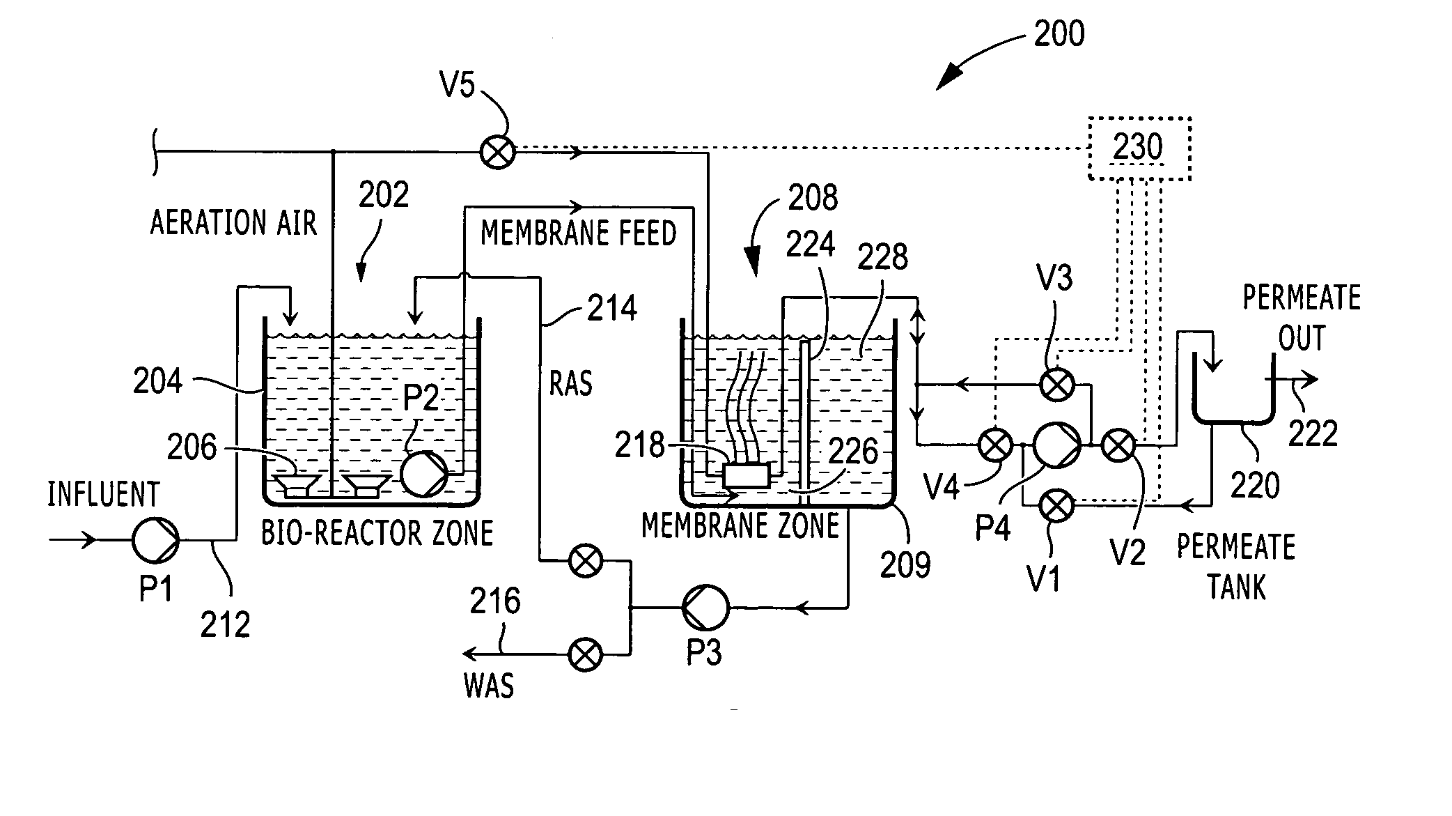
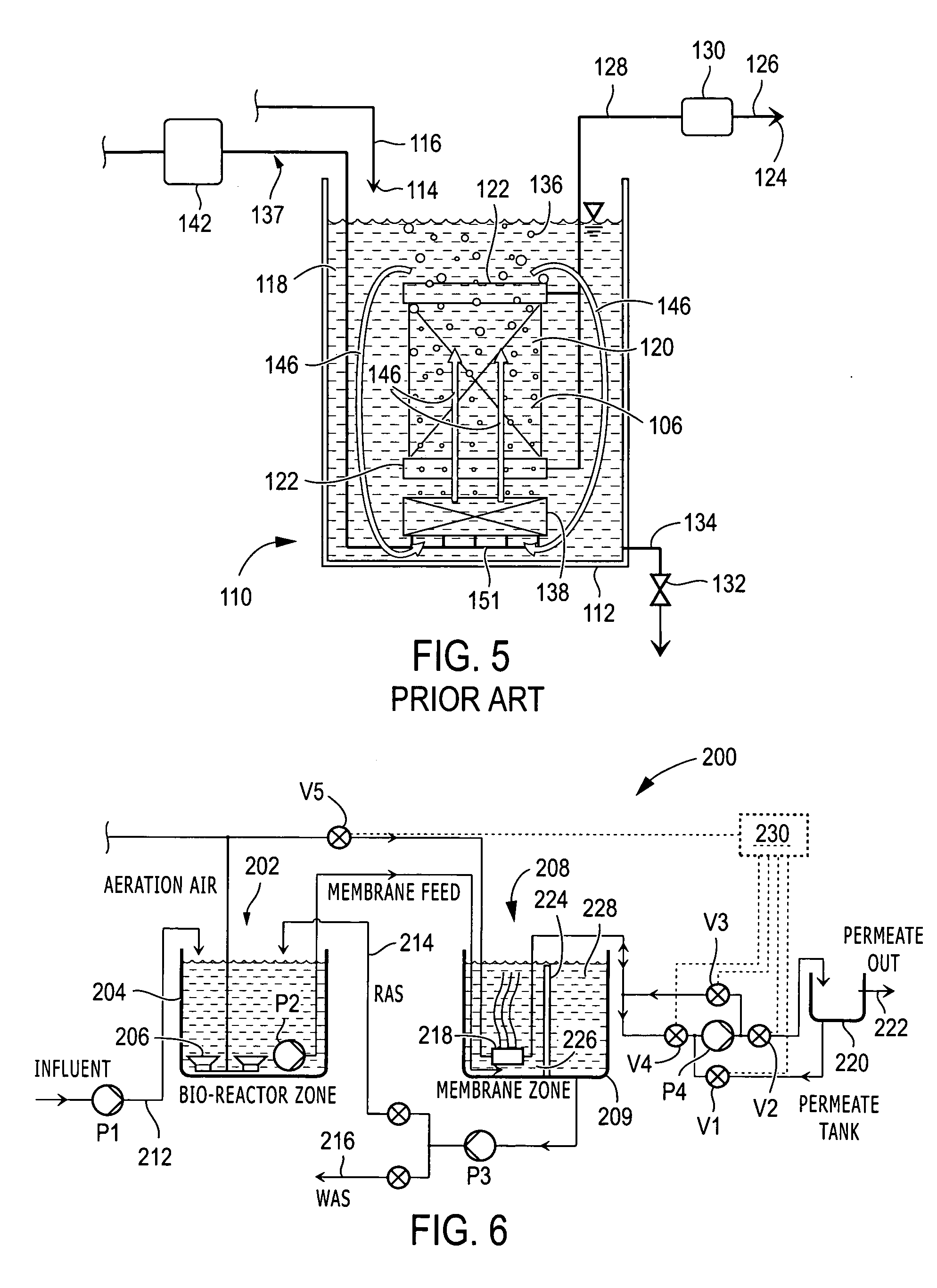
[0059] A pilot study was conducted on an effluent treatment process having municipal raw waste feed of approximately 2-4 gpm, pretreated by coarse screening to 3 mm. The average flow characteristics included BOD5 at 200-300 mg / l, suspended solids at 150-250 mg / l, and ammonia at 25-35 mg / l. The membrane zone of the pilot unit was equipped with hollow fiber ultrafiltration membranes that were installed and optimized to derive the dimensional (positioning from nearest wall, floor, liquid level line) and operational (vertical flow velocity) parameters disclosed and claimed herein. Operation was conducted at an MLSS of between 3,500 and 8,000 mg / l and FM ratios from 0.01 to 1.5. Optimum biological aeration and air scour / backwash efficiency were achieved at a loading F / M ratio of 0.05-5. Cleaning cycles were also optimized in this range. The pilot was operated in both a continuous mode as an MBR and in a cyclic mode as an SMBR (in which the MLSS in the decant / filtration stage was allowed ...


PUM

PropertyMeasurementUnit
Lengthaaaaaaaaaa
Lengthaaaaaaaaaa
Lengthaaaaaaaaaa

Abstract

A membrane filtration system comprising one or more submerged ultrafiltration or microfiltration membrane assemblies at ambient pressure, each membrane assembly positioned 100-240 mm from a nearest wall, baffle, or adjacent membrane assembly and no more than 1 meter above a floor and at least 150 mm below the liquid level. Mixed liquor is discharged underneath each membrane assembly to create a vertical flow velocity in a range of 1-8 mm/second along an entire length of the membrane assembly. In a sequenced batch reactor system, a coarse bubble air diffuser for scouring each membrane assembly is supplied with air only during the backwash cycle of the filtration system and not during the filtration cycle. In a membrane bioreactor system, the biological treatment section is physically separated from the filtration section and fine bubble air diffusion is used in the biological treatment section.

Description

FIELD OF THE INVENTION [0001] This invention relates to membrane filtration, specifically microfiltration and ultrafiltration used in biological treatment processes for effluent treatment. BACKGROUND OF THE INVENTION [0002] Hollow fiber ultrafiltration (UF) or microfiltration (MF) membrane bioreactor (MBR) processes have been used in water and wastewater treatment to provide high levels of finished water treatment. These activated-sludge-type processes typically involve a single basin at ambient pressure containing a series of coarse bubble aeration devices into which single or multiple modules (or groupings) of hollow fiber or plate-type UF or MF membranes are inserted. Waste enters one end of the basin, is mixed with a biomass containing active aerobic organisms, and air is added to provide oxygen. The mixture of biomass and water is referred to as “mixed liquor.” The solids in the mixed liquor are referred to as “mixed liquor suspended solids” (MLSS). During aeration, the membran...

Claims


Application Information

Patent Timeline
IPC IPC(8): C02F3/02
CPCB01D61/145B01D61/147B01D61/18B01D61/20B01D61/22B01D65/02B01D2315/06B01D2321/04B01D2321/12B01D2321/16B01D2321/185C02F1/444C02F1/74C02F3/1263C02F3/1273C02F3/20C02F2203/006C02F2209/005C02F2209/44C02F2303/16C02F2303/20Y02W10/10
Inventor DIMITRIOU, MICHAEL A.KRALL, JOSEPH G.RICE, DAVIDYOGENDRAN, VELUPILLAIBYRNE, ROGER J.GEORGE, KENNETH P.KOCH, JOHN E. III
Owner ITT MFG ENTERPRISES LLC
Why Eureka
Try Eureka