
Catadioptric projection optical system and exposure apparatus having the same

Inactive Publication Date: 2006-04-20
CANON KK
View PDF6 Cites 31 Cited by
  • Summary
  • Abstract
  • Description
  • Claims
  • Application Information

AI Technical Summary

Benefits of technology

[0009] The present invention is directed to a catadioptric projection optical system, an exposure apparatus having the same, and device fabrication method, which shorten the distance (object-to-image distance) between the first object (e.g., a reticle) and the second object (e.g., a wafer) and provides a stable and superior image performance.

Problems solved by technology

However, quartz and calcium fluoride possess similar dispersive powers, and have difficulties in correcting the chromatic aberration, especially, for the optical system that has a very higher NA as in the immersion optical system.
Moreover, a lens diameter increases as the NA becomes higher, and causes the increased apparatus cost.
Especially, when the NA of higher than about 1.1 dramatically increases an object-to-image distance (in other words, a distance between a reticle and a wafer), and an effective diameter of lens inevitably enlarging the optical system and increasing the apparatus cost.
Therefore, the optical system creates a problem of interference between the first object (e.g., a reticle) surface or the reticle stage and the lens or the plane mirror or an insufficient space.
Therefore, it is undesirable for an exposure apparatus that has an optical system with a higher NA by the immersion etc. to arrange the first object (e.g., a reticle) and second object (e.g., a wafer) in not parallel.
If an optical axis of the lens (optical element) having a refractive power is not along the gravity direction, the imaging performance deteriorates by self-weight deformations and influences of retainer.
Due to the strong refractive power of each lens necessary to maintain the size of the optical system with a higher NA, the aberration correction becomes difficult.
As a result, both an incident angle range and the maximum incident angle upon the plane mirror increase, and a higher NA scheme as in the immersion etc. encounters a serious problem.
In other words, both the incident angle range and the maximum incident angle upon the plane mirror considerably increase due to the NA of 1 or higher, and the imaging performance inevitably deteriorates by the influence of a deteriorated property of the plane mirror etc.
Moreover, as the above-mentioned, optical axes of the concave mirror and the negative lens in the second imaging optical system are perpendicular to the gravity direction, and it is not desirable structure to improve a final performance to a limit.

Method used


Image

  • Catadioptric projection optical system and exposure apparatus having the same
  • Catadioptric projection optical system and exposure apparatus having the same
  • Catadioptric projection optical system and exposure apparatus having the same

Examples


first embodiment

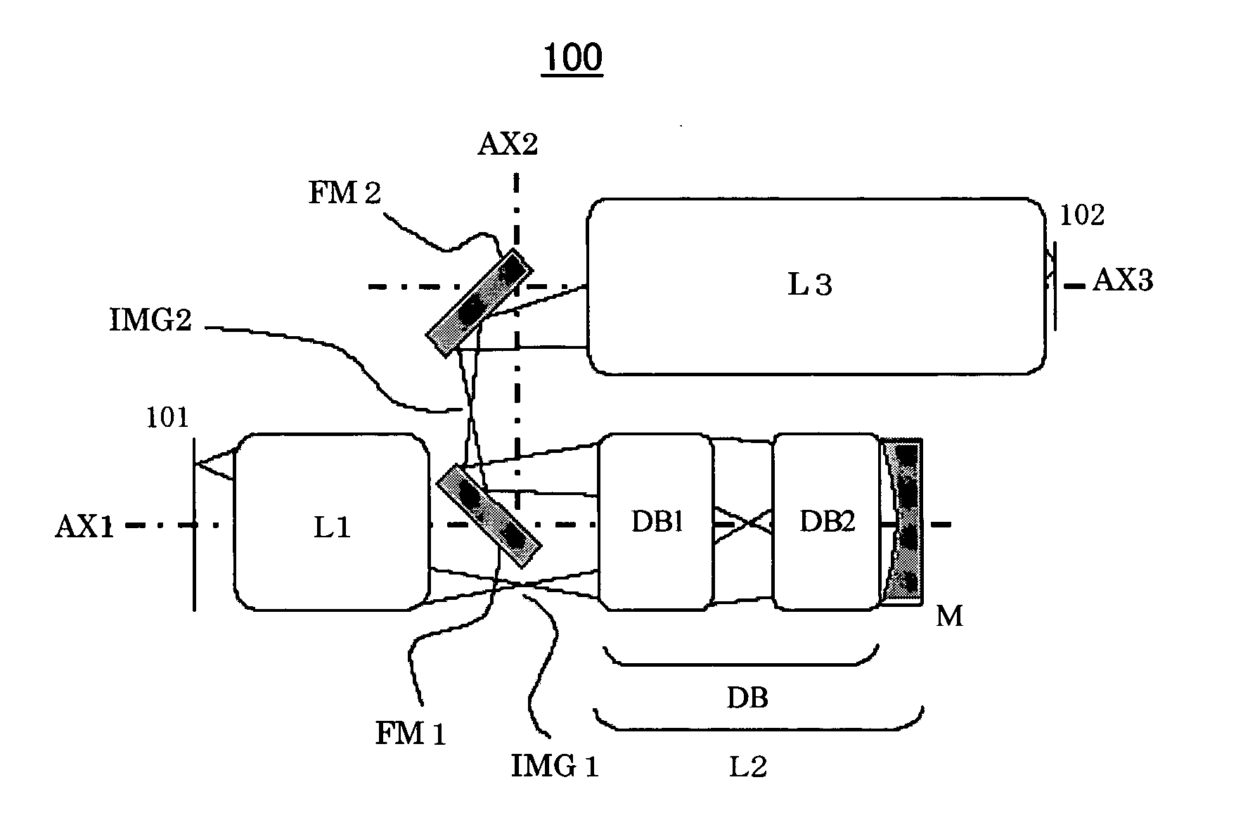
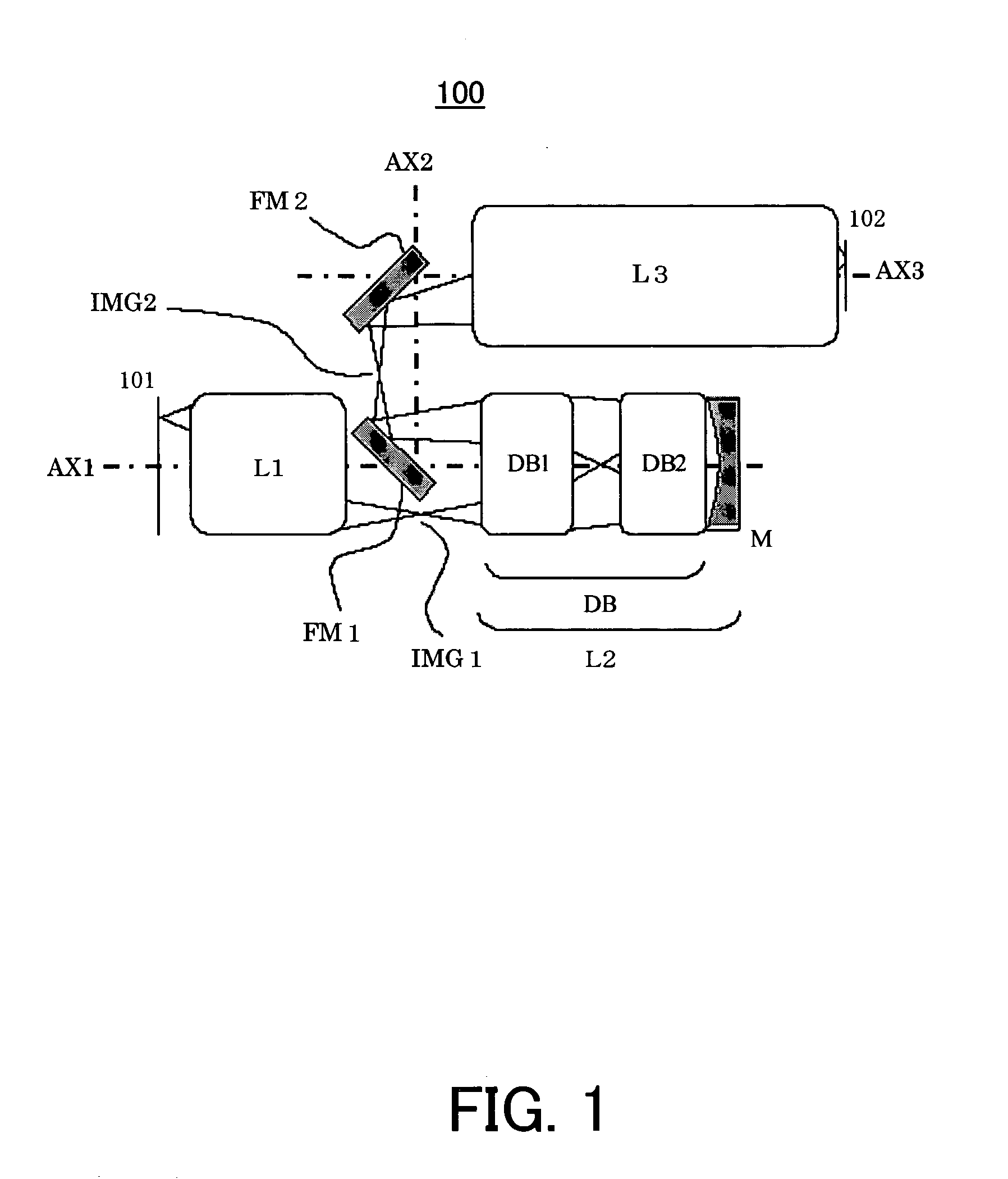
[0081]FIG. 5 is an optical-path diagram showing a configuration of the catadioptric projection optical system 100 of the first embodiment. Referring to FIG. 5, the catadioptric projection optical system 100 includes, in order from the first object 101 side, a lens unit (a first lens unit) L1 that does not form a reciprocating optical system, a catadioptric unit L2 that forms the reciprocating optical system, and a lens unit (a second lens unit) L3 that does not form the reciprocating optical system.

[0082] The lens unit L1 is a dioptric lens unit that includes at least one lens. The catadioptric unit L2 includes a lens unit (a third lens unit) DB that forms the reciprocating optical system and a concave mirror M. Moreover, the lens unit DB includes a lens unit (a fourth lens unit) DB1 having a positive refractive power and a lens unit (a fifth lens unit) DB2 having a negative refractive power. The lens unit L3 is a dioptric lens unit that includes at least one lens.

[0083] The catad...

second embodiment

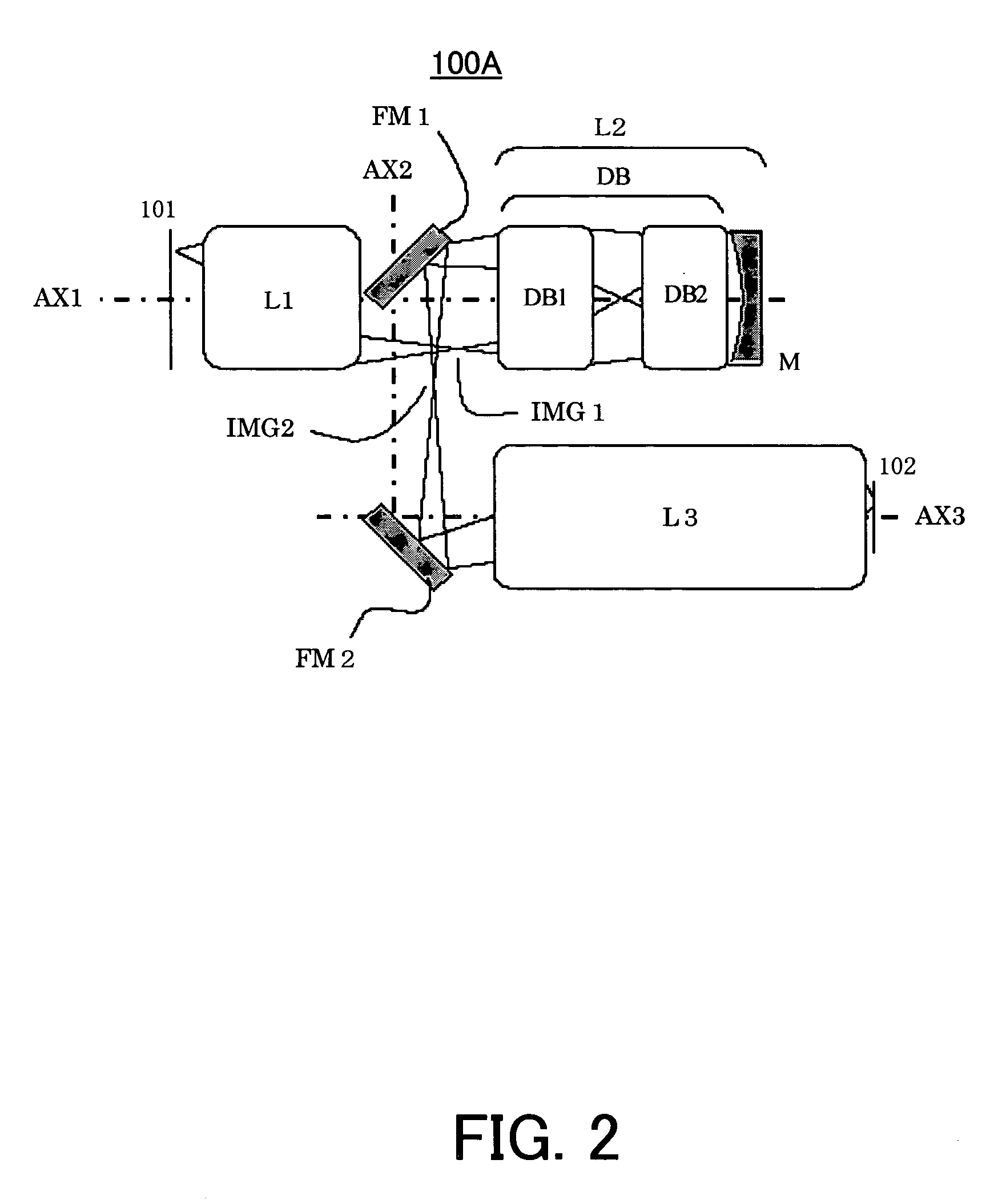
[0098]FIG. 7 is an optical-path diagram showing a configuration of the catadioptric projection optical system 100 of the second embodiment. Referring to FIG. 7, the catadioptric projection optical system 100 includes, in order from the first object 101 side, a lens unit (a first lens unit) L1 that does not form a reciprocating optical system, a catadioptric unit L2 that forms the reciprocating optical system, and a lens unit (a second lens unit) L3 that does not form the reciprocating optical system.

[0099] The lens unit L1 is a dioptric lens unit that includes at least one lens. The catadioptric unit L2 includes a lens unit (a third lens unit) DB that forms the reciprocating optical system and a concave mirror M. Moreover, the lens unit DB includes a lens unit (a fourth lens unit) DB1 having a positive refractive power and a lens unit (a fifth lens unit) DB2 having a negative refractive power. The lens unit L3 is a dioptric lens unit that includes at least one lens.

[0100] The firs...


PUM


Abstract

A catadioptric projection optical system for forming plural intermediate images of a first object and for imaging the image of the first object onto a second object, said catadioptric projection optical system includes at least one concave mirror, a first deflective reflector, and a second deflective reflector, wherein a light reflected by the first deflective reflector is directly led to the second deflective reflector.

Description

BACKGROUND OF THE INVENTION [0001] The present invention relates generally to a projection optical system, and more particularly to a catadioptric projection optical system that projects an object, such as a single crystal substrate and a glass plate for a liquid crystal display (“LCD”), using a mirror. The present invention is suitable, for example, an immersion exposure apparatus (an immersion lithography exposure system) for exposing the object through a liquid between the projection optical system and the object. [0002] The photolithography technology for manufacturing fine semiconductor devices, such as semiconductor memory and logic circuits, has conventionally employed a reduction projection exposure apparatus that uses a projection optical system to project and transfer a circuit pattern of a reticle (or mask) onto a wafer, etc. A more highly integrated and finer semiconductor device (circuit pattern) requires a projection optical system for a better specification and perfor...

Claims


Application Information

Patent Timeline
IPC IPC(8): G02B17/00
CPCG02B17/08G02B17/0892G03F7/70225G03F7/70275
Inventor KATO, TAKASHITERASAWA, CHIAKI
Owner CANON KK
Learn More